
Rusted steel acid pickling device

A pickling device and steel technology, applied in the field of steel processing, can solve the problems of poor rust removal effect and long pickling time, and achieve the effects of high work efficiency, good pickling and reasonable design

Inactive Publication Date: 2020-08-04
司秀玲
View PDF0 Cites 0 Cited by
  • Summary
  • Abstract
  • Description
  • Claims
  • Application Information

AI Technical Summary

Problems solved by technology

[0003] Steel will be rusted in a humid environment or in a high temperature environment. Corroded steel must be derusted before use. Pickling is a common derusting process. Although the existing pickling equipment can be used for derusting, but Long pickling time, poor rust removal effect

Method used


Image

  • Rusted steel acid pickling device
  • Rusted steel acid pickling device
  • Rusted steel acid pickling device

Examples


Embodiment 1

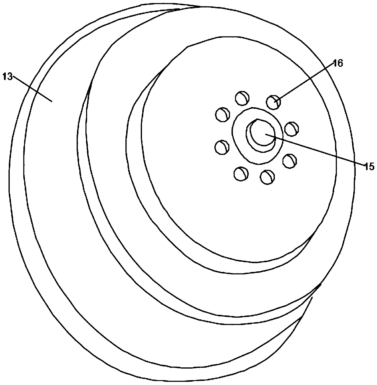
[0023] A corroded steel pickling device includes a frame 5, a rotating electric machine 1, a cleaning box 4, and a control panel 14. The cleaning box 4 is installed in the frame 5 and the output end of the rotating electric machine 1 is connected with a rotating shaft 2 and a rotating shaft 2 The lower end is inserted into the cleaning box 4 and the grinding parts 3 are evenly distributed on the rotating shaft 2. The top end of the inner wall of the frame 5 is symmetrically installed with an electric cylinder 6, and the output end of each electric cylinder 6 is equipped with an electric push rod 7, each The bottom end of the electric push rod 7 is connected with the bottom of the inner wall of the frame 5 through an elastic member 8. The side of each electric push rod 7 is installed with an arc plate 9 and each arc plate 9 is provided with an arc groove 10. Each arc-shaped slot 10 is slidably installed with a sliding member 11, each sliding member 11 is connected to the outer wa...

Embodiment 2

[0029] A corroded steel pickling device includes a frame 5, a rotating electric machine 1, a cleaning box 4, and a control panel 14. The cleaning box 4 is installed in the frame 5 and the output end of the rotating electric machine 1 is connected with a rotating shaft 2 and a rotating shaft 2 The lower end is inserted into the cleaning box 4 and the grinding parts 3 are evenly distributed on the rotating shaft 2. The top end of the inner wall of the frame 5 is symmetrically installed with an electric cylinder 6, and the output end of each electric cylinder 6 is equipped with an electric push rod 7, each The bottom end of the electric push rod 7 is connected with the bottom of the inner wall of the frame 5 through an elastic member 8. The side of each electric push rod 7 is installed with an arc plate 9 and each arc plate 9 is provided with an arc groove 10. Each arc-shaped slot 10 is slidably installed with a sliding member 11, each sliding member 11 is connected to the outer wa...


PUM


Abstract

The invention discloses a rusted steel acid pickling device to solve the problem that an existing acid pickling device is poor in rust removing effect. The rusted steel acid pickling device comprisesa frame, a rotating motor, a cleaning tank and a control panel. The output end of the rotating motor is connected with a rotating shaft, the lower end of the rotating shaft is inserted in the cleaningtank, and polishing parts are evenly distributed on the rotating shaft. Electric air cylinders are installed at the top end of the inner wall of the frame, and the output end of each electric air cylinder is provided with an electric push rod. The bottom end of each electric push rod is connected with the bottom of the inner wall of the frame through an elastic part, and an arc plate is installedat the side portion of each electric push rod. Each arc plate is provide with an arc groove, a sliding part is installed in each arc groove in a sliding manner, and each sliding part is connected with the outer wall of the cleaning tank through a fixing rod. When the polishing parts are used for polishing the surface of rusted steel, the cleaning tank is further driven to wobble left and right atthe same time, acid pickling liquid can conduct acid pickling on the rusted steel better, the acid pickling process is accelerated, and the work efficiency is high.

Description

Technical field [0001] The invention relates to the field of steel processing, in particular to a corroded steel pickling device. Background technique [0002] Steel is a material with a certain shape, size and performance made by steel ingots, billets or steel through pressure processing. With its low price and reliable performance, steel has become one of the most used materials in the world. It is used in the construction industry, manufacturing industry and people. An indispensable ingredient in daily life. [0003] Steel will rust in a humid environment or a high temperature environment. Rusted steel must be derusted before use. Pickling is a common derusting process. Although the existing pickling device can be used for derusting, The pickling time is long and the rust removal effect is poor. Summary of the invention [0004] The purpose of the embodiments of the present invention is to provide a corroded steel pickling device to solve the problems raised in the background a...

Claims


Application Information

Patent Timeline
Patent Type & Authority Applications(China)
IPC IPC(8): C23G3/00B24B27/033B24B41/04B24B47/12
CPCB24B27/033B24B41/04B24B47/12C23G3/00
Inventor 司秀玲
Owner 司秀玲
Learn More