Cold-rolled sheet manufacturing device

A manufacturing device and technology for cold-rolled sheets, which are applied in the field of pickling equipment for cold-rolled sheet manufacturing, can solve the problems of poor surface cleaning effect of cold-rolled sheets, poor liquid up and down flow conditions, influence on the degree of pickling balance, etc., so as to prevent impurities The effect of depositing, preventing the accumulation of impurities, and promoting flow

Inactive Publication Date: 2021-01-15
王东亮
View PDF0 Cites 1 Cited by
  • Summary
  • Abstract
  • Description
  • Claims
  • Application Information

AI Technical Summary

Problems solved by technology

[0002] In the manufacturing process of cold-rolled sheet, it is necessary to pickle the quenched sheet body to remove the oxide layer on the surface to facilitate subsequent processing. Recoil again to complete the pickling process of the cold-rolled sheet, but during the immersion cleaning process, for the lower surface of the cold-rolled sheet, since the liquid is injected from below, and the liquid near the pickling falls under gravity, the cleaning effect It can meet the requirements, but for the upper surface of the cold-rolled plate, the nearby pickling solution flows poorly, and in the process of long-term pickling, the cleaning effect of the surface of the cold-rolled plate is poor, and artificial timing disturbance is required. Secondly, impurity particles will accumulate on the upper surface, so that the board still needs to be scraped and cleaned after being sent out. In addition, in the prior art, the entire cleaning pool is blocked by the water flow due to the large surface area of ​​the board, so that the liquid flows up and down. Poor, also affects the balance of pickling

Method used


Image

  • Cold-rolled sheet manufacturing device
  • Cold-rolled sheet manufacturing device
  • Cold-rolled sheet manufacturing device

Examples


Embodiment Construction

[0027] The following description serves to disclose the present invention to enable those skilled in the art to carry out the present invention. The preferred embodiments described below are only examples, and those skilled in the art can devise other obvious variations.

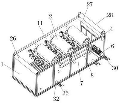
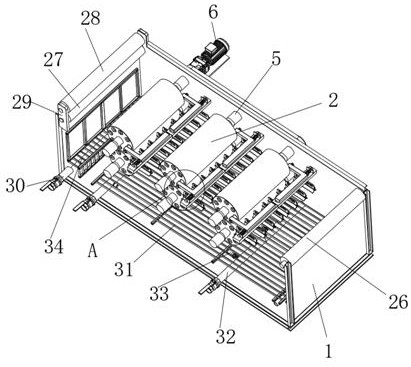
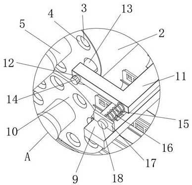
[0028] Such as Figure 1-Figure 7 A cold-rolled sheet manufacturing device shown includes a device main body 1, and several extrusion and pushing mechanisms are arranged on the inner side of the device main body 1. The extrusion and pushing mechanism includes an upper pressure roller 2 installed on the inner side of the device main body 1 in a corresponding rotation up and down. With the lower pressure roller 10, the upper pressure roller 2 and the inner side of the lower pressure roller 10 are respectively provided with several flow guide channels 3 arranged in an annular array, and the flow guide channels 3 are helical with a pitch greater than that of the upper pressure roller 2, and the guide channels T...


PUM


Abstract

The invention relates to the field of cold-rolled sheet manufacturing and pickling equipment, in particular to a cold-rolled sheet manufacturing device which comprises a device body. A plurality of extrusion pushing mechanisms are distributed on the inner side of the device body, and each extrusion pushing mechanism comprises an upper pressing roller and a lower pressing roller which are vertically, correspondingly and rotationally installed on the inner side of the device body. The inner side of the upper pressing roller and the inner side of the lower pressing roller are each provided with aplurality of flow guide channels distributed in an annular array mode, each flow guide channel is in a spiral shape with the screw pitch larger than that of the upper pressing roller, and the two ends of each flow guide channel penetrate through the outer surfaces of the two sides of the upper pressing roller or the lower pressing roller. Each extrusion pushing mechanism further comprises a fixing frame with the two ends fixedly connected to the inner walls of the two sides of the device body, the fixing frame is located in front of the upper pressing roller, and a sliding opening is formed in the upper end face of the fixing frame. The device is beneficial to flowing of the whole pickling solution in the pickling process, flowing of the pickling solution near the upper surface of the plate, cleaning of the surface of the plate and long-term use.

Description

technical field [0001] The invention relates to the field of cold-rolled sheet manufacturing pickling equipment, in particular to a cold-rolled sheet manufacturing device. Background technique [0002] In the manufacturing process of cold-rolled sheet, it is necessary to pickle the quenched sheet body to remove the oxide layer on the surface to facilitate subsequent processing. Recoil again to complete the pickling process of the cold-rolled sheet, but during the immersion cleaning process, for the lower surface of the cold-rolled sheet, since the liquid is injected from below, and the liquid near the pickling falls under gravity, the cleaning effect It can meet the requirements, but for the upper surface of the cold-rolled plate, the nearby pickling solution flows poorly, and in the process of long-term pickling, the cleaning effect of the surface of the cold-rolled plate is poor, and artificial timing disturbance is required. Secondly, impurity particles will accumulate o...

Claims


Application Information

Patent Timeline
IPC IPC(8): C23G1/08C23G3/02
CPCC23G1/08C23G3/023C23G3/025
Inventor 不公告发明人
Owner 王东亮
Why Eureka
Try Eureka