A fence for animal husbandry
A technology for animal husbandry and fencing, applied in the field of fencing, can solve the problems of livestock escape and climbing in the fence, and achieve the effect of preventing livestock from escaping and improving the blocking effect.
- Summary
- Abstract
- Description
- Claims
- Application Information
AI Technical Summary
Problems solved by technology
Method used
Image
Examples
Embodiment 1
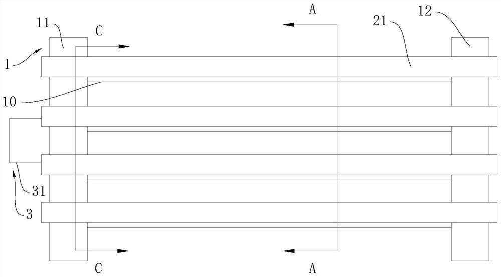
[0026] Such as figure 1 As shown, a fence for animal husbandry provided by the embodiment of the present invention includes a support device 1 and a steel pipe 10;
[0027] The support device 1 includes a first bracket 11 and a second bracket 12, the first bracket 11 and the second bracket 12 are fixedly arranged on the ground, and the two ends of the steel pipe 10 penetrate to the inside of the first bracket 11 and the second bracket 12 respectively, and the steel pipe The two ends of 10 are respectively rotatably arranged on the first bracket 11 and the second bracket 12, and the steel pipes 10 are arranged vertically and uniformly between the first bracket 11 and the second bracket 12; the supporting device 1 is arranged obliquely , the supporting device 1 is inclined towards the inner circle of the fence; the steel pipe 10 is a hollow steel pipe 10 .
[0028] Working principle: In the area corresponding to the installation point of the device, a rotatable steel pipe is ar...
Embodiment 2
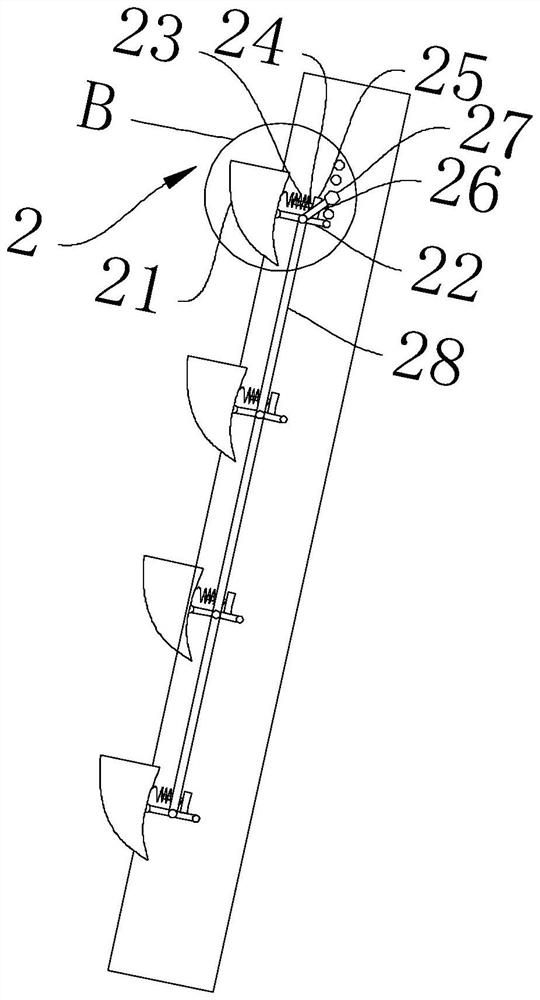
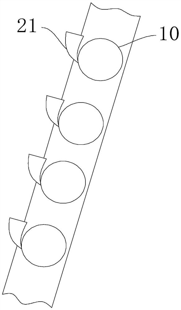
[0030] On the basis of Example 1, such as Figure 1 to Figure 4 As shown, the support device 1 is provided with a cleaning device 2, the cleaning device 2 includes a scraper 21 and a connecting device, the connecting device is respectively arranged on the first bracket 11 and the second bracket 12, and the connecting device includes a first connecting rod 22, a return spring 23. Support rod 24 and support seat 25, one end of the first connecting rod 22 is rotatably arranged on the surface of the second support 12, and the other end is rotatably connected to the scraper 21, and the support seat 25 is fixedly arranged on the surface of the first connecting rod 22 away from On one end of the scraper 21, the support rod 24 is fixedly arranged on the support base 25, the return spring 23 is sleeved on the support rod 24, one end of the return spring 23 is fixedly connected to the upper end of the scraper 21, and the other end is fixedly connected to the support base 25 ; The cleani...
Embodiment 3
[0034] On the basis of Example 2, such as Figure 5 to Figure 7 As shown, the rotating device 3 includes a motor 31 and a gear set, the motor 31 is fixedly arranged on the first bracket 11, and a cavity 111 is provided inside the first bracket 11, the gear set includes a driving wheel 32 and a drive wheel mechanism, and the drive wheel mechanism includes The first transmission mechanism 33 and the second transmission mechanism 34, the driving wheel 32 is drivingly connected with the output end of the motor 31, the first transmission mechanism 33 and the second transmission mechanism 34 all include an outer ring gear, an inner ratchet and a ratchet, and the outer ring gear It is set coaxially with the inner ratchet, the pawl is rotatably arranged on the inner wall of the outer ring gear, the inner ratchet of the first transmission mechanism 33 is fixedly arranged in the cavity 111, and the outer ring gear of the first transmission mechanism 33 is rotatably arranged In the cavit...
PUM
 Abstract
Description
Claims
Application Information
 - R&D
- Intellectual Property
- Life Sciences
- Materials
- Tech Scout
- Unparalleled Data Quality
- Higher Quality Content
- 60% Fewer Hallucinations
Browse by: Latest US Patents, China's latest patents, Technical Efficacy Thesaurus, Application Domain, Technology Topic, Popular Technical Reports.
© 2025 PatSnap. All rights reserved.Legal|Privacy policy|Modern Slavery Act Transparency Statement|Sitemap|About US| Contact US: help@patsnap.com


