
Optical module

An optical module and backlight technology, applied in the field of optical modules, can solve problems such as signal crosstalk between channels, inability to drill ground holes, and small space for ground holes

Inactive Publication Date: 2020-07-28
HISENSE BROADBAND MULTIMEDIA TECH
View PDF8 Cites 3 Cited by
  • Summary
  • Abstract
  • Description
  • Claims
  • Application Information

AI Technical Summary

Problems solved by technology

[0004] However, with the development of modules in the direction of miniaturization, the size of ceramic substrates and circuit boards is also getting smaller and smaller, resulting in thinner ground wires near the bonding pads, which in turn makes the space for ground holes too small, resulting in The ground hole cannot be drilled at the position of the wire pad, resulting in a longer signal return path and serious signal crosstalk between channels

Method used

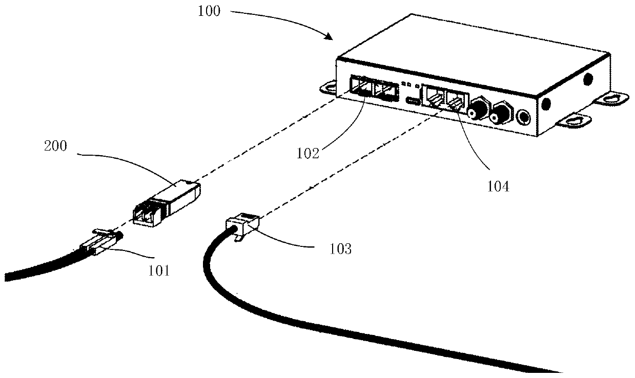
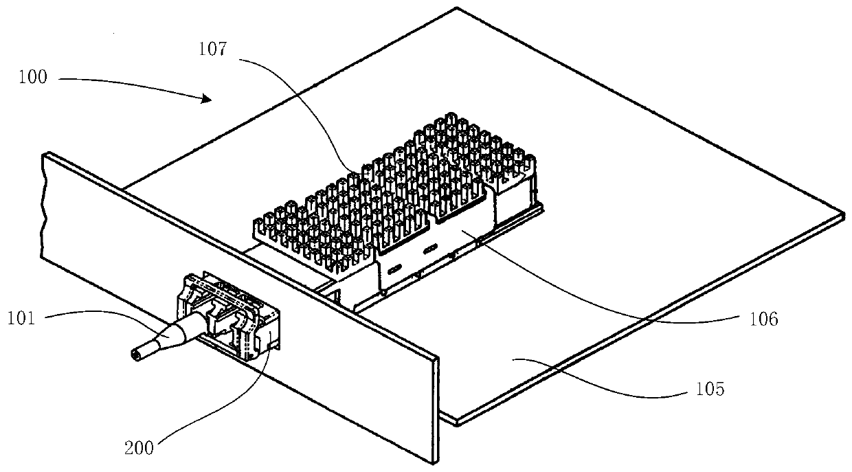
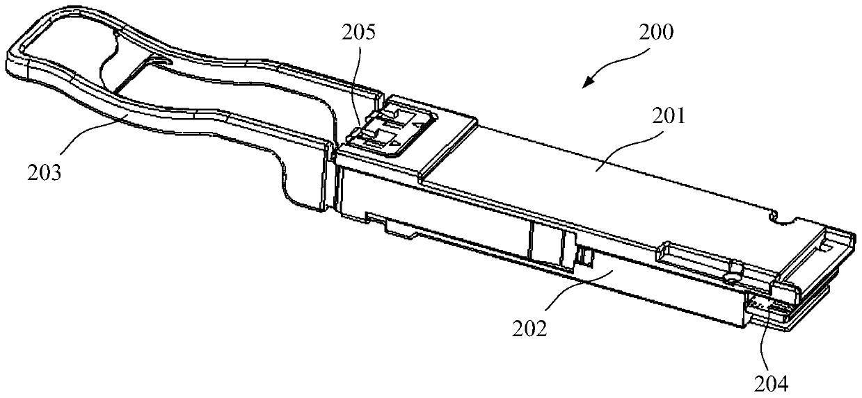

Image

  • Optical module
  • Optical module
  • Optical module

Examples


Embodiment Construction

[0026] The following will clearly and completely describe the technical solution in this embodiment with reference to the drawings in this embodiment. Obviously, the described embodiment is only a part of the embodiments of the present invention, but not all of them. Based on the embodiments in this application, all other embodiments obtained by persons of ordinary skill in the art without making creative efforts fall within the protection scope of the present invention.

[0027] One of the core links of optical fiber communication is the conversion of photoelectric signals. Optical fiber communication uses optical signals carrying information to be transmitted in optical fibers / optical waveguides, and low-cost, low-loss information transmission can be achieved by using the passive transmission characteristics of light in optical fibers. However, information processing equipment such as computers use electrical signals, which requires mutual conversion between electrical signa...


PUM


Abstract

The invention provides an optical module. The optical module comprises a circuit board, a gasket and a laser chip arranged on the gasket. The circuit board is connected with the gasket; a first gasketground wire on the gasket is connected with a first circuit board ground wire on the circuit board, a gasket high-speed signal wire on the gasket is connected with a circuit board high-speed signal wire on the circuit board, and a second gasket ground wire on the gasket is connected with a second circuit board ground wire on the circuit board in a routing mode. High-frequency data electric signals on the circuit board are sent out of a laser chip, and the first gasket ground wire and the second gasket ground wire on the two sides of the high-speed signal wire on the gasket or the first gasketground wire on the gasket and the second circuit board ground wire on the circuit board are connected together through the bonding wires respectively, so that the length of a backflow path of a high-frequency signal can be effectively reduced, and signal crosstalk between channels is prevented.

Description

technical field [0001] The present application relates to the technical field of optical fiber communication, and in particular to an optical module. Background technique [0002] Due to the increasingly high requirements for communication bandwidth in the field of optical fiber communication, the global optical communication is in a period of rapid development. In the field of high-speed data communication, in order to ensure long-distance high-speed transmission of data, optical modules are usually used in this field to realize the transmission and reception of light of different wavelengths. [0003] Existing optical modules usually refer to integrated modules used for photoelectric conversion. For optical signal transmission, laser chips are usually used to convert electrical signals from the host computer into optical signals. In order to provide a flat optical bearing surface for the laser chip, the laser chip is usually arranged on a ceramic substrate, and high-speed...

Claims


Application Information

Patent Timeline
IPC IPC(8): G02B6/42
CPCG02B6/428G02B6/4279G02B6/4277H01S5/0239H01S5/02345H01S5/06226H05K1/142H05K2203/049H05K1/0219H05K2201/0979H01S5/02253H01S5/0261H01S5/0264
Inventor 王欣南李丹董本正张加傲慕建伟
Owner HISENSE BROADBAND MULTIMEDIA TECH
Learn More