
Steel box arch bridge arch rib segmental vertical rotation structure and construction method

A segmented and vertical rotation technology, applied in the direction of arch bridges, bridges, bridge materials, etc., can solve the problems of large vertical lifting load of arch ribs, large manual input of materials, and large height of assembled supports, so as to avoid construction and facilitate construction Fast and reduce the amount of support engineering

Pending Publication Date: 2020-07-28
ROAD & BRIDGE INT +1
View PDF0 Cites 3 Cited by
  • Summary
  • Abstract
  • Description
  • Claims
  • Application Information

AI Technical Summary

Problems solved by technology

[0004] In view of this, in order to solve the problems that the vertical rotation construction of arch ribs in the existing river valley terrain is limited by the terrain, there are large heights of assembled supports, large manual input of materials, large lifting loads of vertical rotation of arch ribs, and relatively large construction safety risks. Segmental vertical rotation structure and construction method of arch ribs of steel box arch bridges with convenient construction, safety and reliability, less material input and convenient arch bridge closure

Method used


Image

  • Steel box arch bridge arch rib segmental vertical rotation structure and construction method
  • Steel box arch bridge arch rib segmental vertical rotation structure and construction method
  • Steel box arch bridge arch rib segmental vertical rotation structure and construction method

Examples


Embodiment Construction

[0034] Embodiments of the present invention are described below through specific examples, and those skilled in the art can easily understand other advantages and effects of the present invention from the content disclosed in this specification. The present invention can also be implemented or applied through other different specific implementation modes, and various modifications or changes can be made to the details in this specification based on different viewpoints and applications without departing from the spirit of the present invention. It should be noted that the diagrams provided in the following embodiments are only schematically illustrating the basic concept of the present invention, and the following embodiments and the features in the embodiments can be combined with each other in the case of no conflict.

[0035] Wherein, the accompanying drawings are for illustrative purposes only, and represent only schematic diagrams, rather than physical drawings, and should...


PUM


Abstract

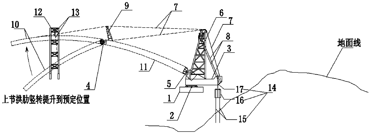
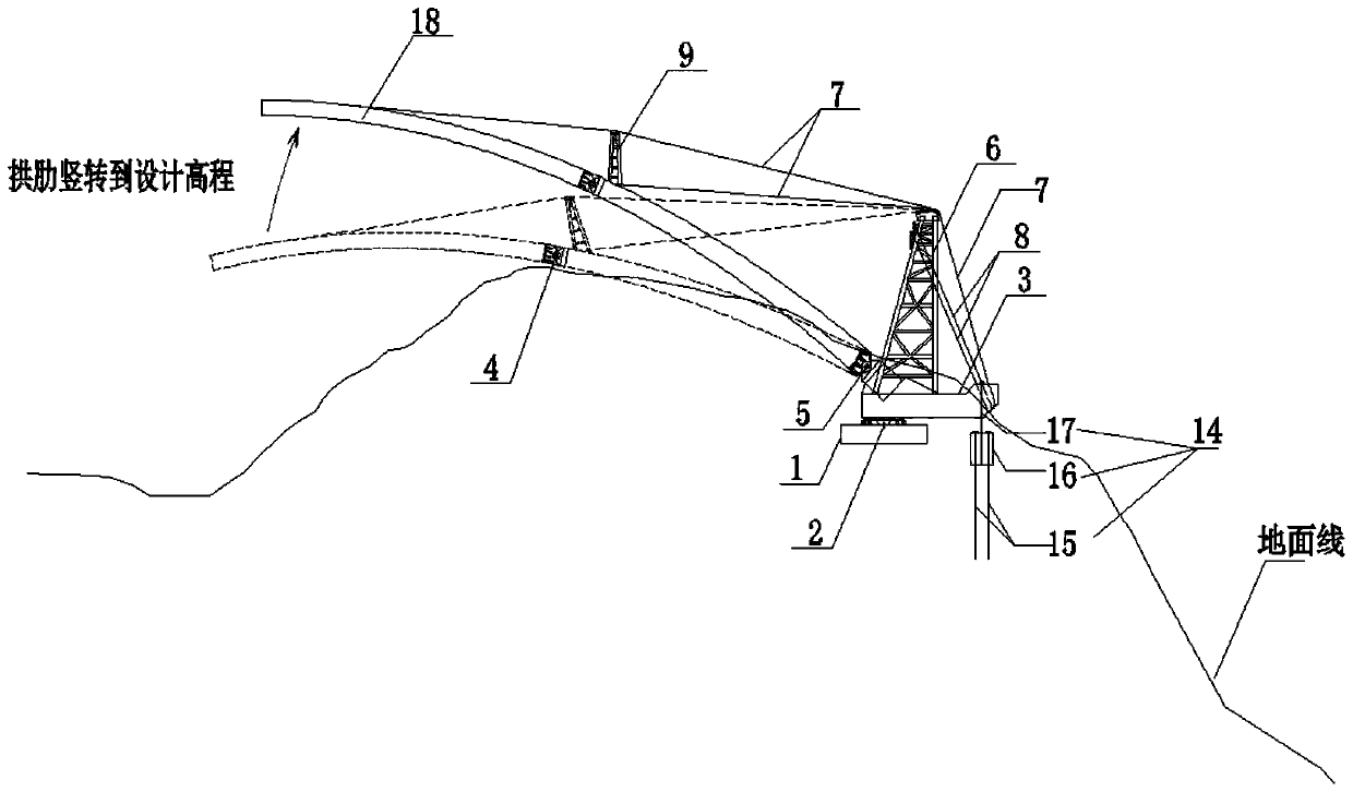
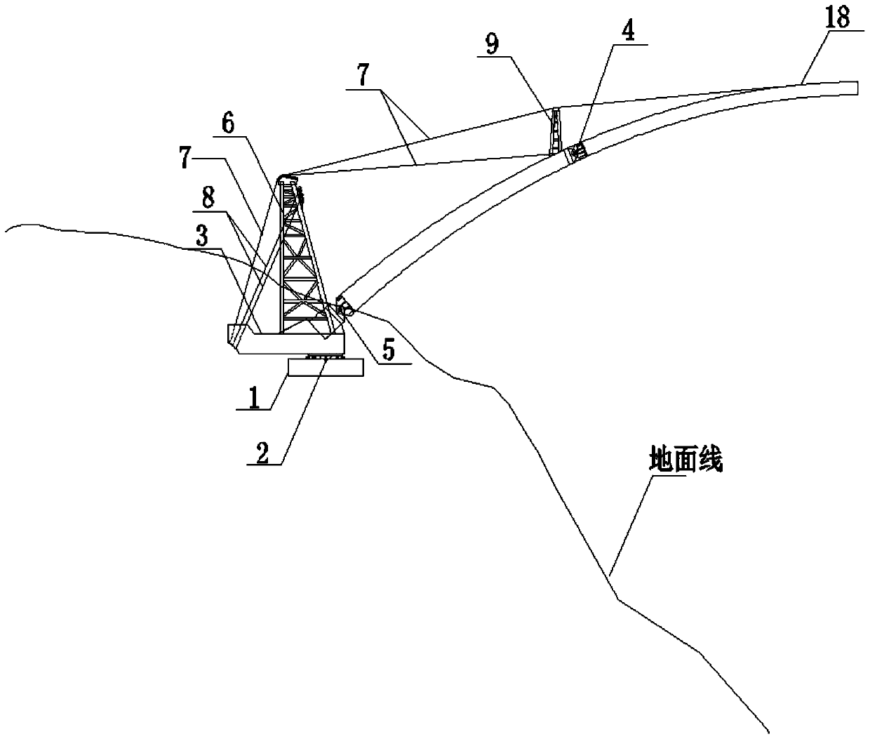
The invention belongs to the technical field of arch bridge construction, and relates to a steel box arch bridge arch rib segmental vertical rotation structure and a construction method, the steel boxarch bridge arch rib segmental vertical rotation structure comprises a horizontal rotating system used for completing arch rib plane rotation and a vertical rotating system used for completing lifting and lowering in an arch rib vertical plane; the horizontal rotating system comprises a lower rotating disc, a horizontal rotating system, an upper rotating disc and a traction system; the arch rib is divided into an upper section arch rib and a lower section arch rib; the vertical rotating system comprises an integral arch rib vertical rotating hinge used for fixing the lower section arch rib, asection arch rib vertical rotating hinge which is installed at the joint of the upper section arch rib and the lower section arch rib, a buckling cable, a buckling tower and a rear anchoring system.A lifting tower frame and a lifting cable which is arranged on the lifting tower frame and is used for controlling the upper section arch rib are arranged below the upper section arch rib; a balance cable is installed between the inner side of the upper portion of the buckling tower and the outer side of the upper rotary disc, and the problems that existing valley terrain arch rib vertical rotation construction is limited by terrain, the height of an assembled support is large, material labor input is large, arch rib vertical rotation lifting loads are large, and construction safety risks arelarge are solved.

Description

technical field [0001] The invention belongs to the technical field of arch bridge construction, and relates to a segmental vertical rotation structure of arch ribs of steel box arch bridges and a construction method. Background technique [0002] With the application of steel structures on various bridges, the spanning capacity of the bridge has been greatly improved, and the stability of the load-bearing structure of the bridge has been increased. The steel box arch has been favored by bridge designers for its strong spanning capacity. Due to the constraints of terrain, climate, geology and hydrology, arch bridges are often constructed using the swivel construction method. Before the construction of the arch ribs, the arch ribs are usually assembled by using the terrain behind or on the side of the abutment turntable and erecting brackets, and then a series of swivels are carried out. construction. Due to the terrain limitation of the abutment area, the assembly of the ar...

Claims


Application Information

Patent Timeline
Patent Type & Authority Applications(China)
IPC IPC(8): E01D21/08E01D4/00E01D2/04E01D101/30
CPCE01D21/08E01D4/00E01D2/04E01D2101/30
Inventor 王阅章鲜正洪陈松洲黄灿李鸣李志文闫少泽张立爽刘治宏王宇航
Owner ROAD & BRIDGE INT
Learn More