


Quick Research
Generate reliable direction feasibility study reports for your R&D in just a few steps.

Technical Q&A
Discover and master advanced knowledge NOW. Basics, ideas, possibilities, all at once.

Find Solutions
As an expert in R&D theories, this can generate solutions to your technical problems instantly.

Evaluate Feasibility
Analyze your overall solution with one click, know your potential R&D risks in advance.

Monitor Landscape
Get weekly tech updates, stay abreast of the latest tech innovations and key insights.
A wire rope cutting, clamping, straightening, tensioning combination device and its use method
A combined device and steel wire rope technology, applied in the field of steel wire rope, can solve the problems of complex structure, single function of the device, and inapplicability to automatic production lines, etc., and achieve the effect of good structural combination
- Summary
- Abstract
- Description
- Claims
- Application Information
AI Technical Summary
Problems solved by technology
Method used
Image

Examples
Embodiment 1
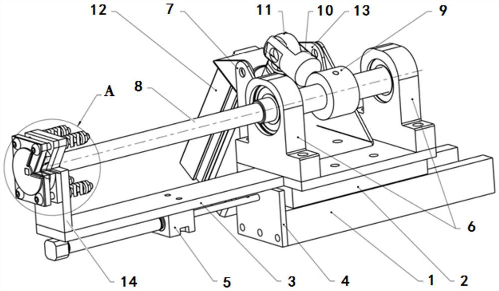
[0052] In Example 1, a device structure capable of fully achieving cutting, clamping, correction, and pulling all functions is provided.
[0053] Such as figure 1 As shown, the apparatus includes a guide rail 1 mounted on the substrate, and there is a guide rail 1 on the rail 1, the guide rail slide 2 can be straight on the guide rail 1, and the guide rail slide 2 is fixed and installed. The mounting plate 3; the guide rail 1 fixed to the piston rod mounting plate 4, the piston rod of the No. 1 cylinder 5 is fixed to the piston rod mounting plate 4, and the cylinder of the No. 1 cylinder 5 is fixed at the bottom of the mounting plate 3, when the cylinder 5 is working Due to the reaction of the force, the piston rod does not move, the cylinder moves, and the mounting plate 3 and the guide slide 2 are thrown. The benefits of this design are: First, the fixed support of the cylinder can be reduced; Second, save the mounting space of the cylinder; three, the cylinder can be removed to...
Embodiment 2
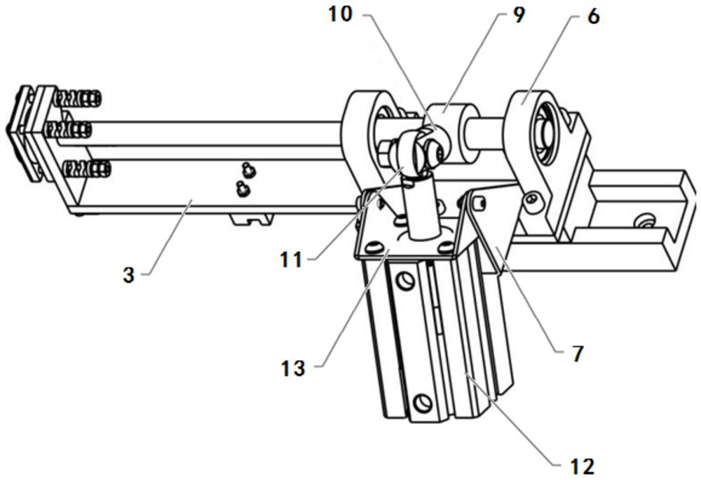
[0087] In Example 2, a device structure that implements cut, clamping, tightening, such as Figure 7 Indicated.
[0088] The difference from the first embodiment is that the correction plate 1 18, the correction plate 2 19 is removed, and the rotary axle side of the rotating shaft shaft end is cut off in the clamp assembly, the cutting plate 15 is cut off the plate 16, and the clamping plate 16 is cut. The clamping plate 17, the bolt 20, the spring 21, and the nut 22.
[0089] BE THE INVENTION Referring to Example 1, cutting the clamping support plate 14 is cut through a plurality of bolts, cutting the clamping plate 16, the clamping plate 17, the spring 21, and the nut 22, which do not move with the rotating shaft; adjust the cut by the spring 21 The clamping force of the plate 15 and the clamp plate 17 is cut off the preload of the clamping plate 16; the cutting of the clamping plate 16 is rotated by the rotating shaft 8, and the stainless steel wire rope is placed in the cut cla...
Embodiment 3
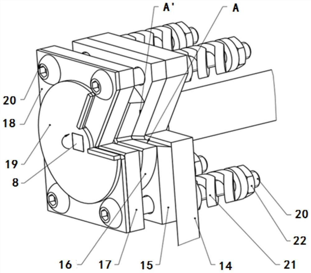
[0091] In Embodiment 3, a device structure that only achieves only cut and clamping is provided.
[0092] Example 3 Different from Example 1 is that the guide rail 1, the guide rail slide 2, the No. 1 cylinder 5, retain the mounting plate 3 and the cut clamping support plate 14, the bearing assembly and the second cylinder assembly are mounted directly in the mounting plate 3. On the upper, the rotary axle side of the rotating axle side is cut into the clamping assembly is mounted to cut the clamping support plate 14, the cutting plate 15 is cut off the clamping plate 16, and the clamping plate 17 is locked by the bolt 20, the spring 21 and the nut 22.
[0093] in working:
[0094] 1. Firstly, the second cylinder device 12 is used to rotate through the fidilizing shaft 10, the connection rod 10, the fixed ring 9 drive the rotary shaft 8, and the cutting clamping plate 16 is rotated, so that the cut clamping plate 16 gap and cut clamping The plate 14, the cutting plate 15 and the c...
PUM
 Abstract
Description
Claims
Application Information
 - R&D Engineer
- R&D Manager
- IP Professional
- Industry Leading Data Capabilities
- Powerful AI technology
- Patent DNA Extraction
Browse by: Latest US Patents, China's latest patents, Technical Efficacy Thesaurus, Application Domain, Technology Topic, Popular Technical Reports.
© 2024 PatSnap. All rights reserved.Legal|Privacy policy|Modern Slavery Act Transparency Statement|Sitemap|About US| Contact US: help@patsnap.com