A three-terminal s-type ring quantum cascade laser
A quantum cascade and laser technology, applied to lasers, phonon exciters, laser components, etc., to achieve the effect of high universality and simplified device structure design
- Summary
- Abstract
- Description
- Claims
- Application Information
AI Technical Summary
Problems solved by technology
Method used
Image
Examples
Embodiment 1
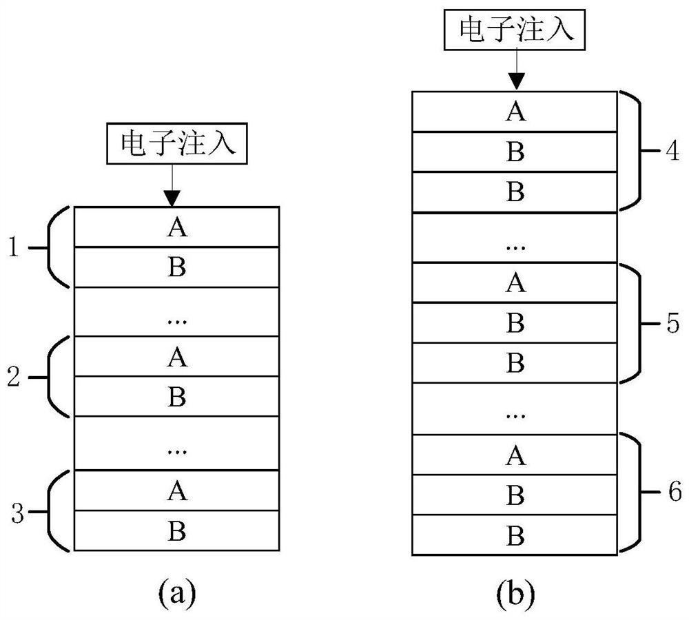
[0064] Such as figure 1 As shown, the schematic diagrams of two arrangement structures of the quantum cascade structure layer 9 in this embodiment, wherein, figure 1 The QCL stack units in (a) are all AB stacks, including the first QCL stack unit AB1, the i-th QCL stack unit AB2; the Nth QCL stack unit AB3, the quantum cascade structure layer 9 consists of N aforementioned QCL stacks Units are stacked to form an AB / … / AB / … / AB stack structure. figure 1 The QCL stack units in (b) are all ABB stacks, including the first QCL stack unit ABB4, the i-th QCL stack unit ABB5, and the N-th QCL stack unit ABB6. The quantum cascade structure layer 9 consists of N aforementioned QCL stacks Units are stacked to form an ABB / … / ABB / … / ABB stack structure.
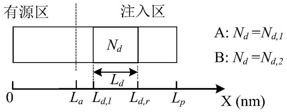
[0065] figure 1 (a), figure 1 Each QCL stack unit in (b) only contains two types of QCL subunits, A and B, and the two types of QCL subunits are composed of active regions and implanted regions, and the implanted regions only contain...
Embodiment 2
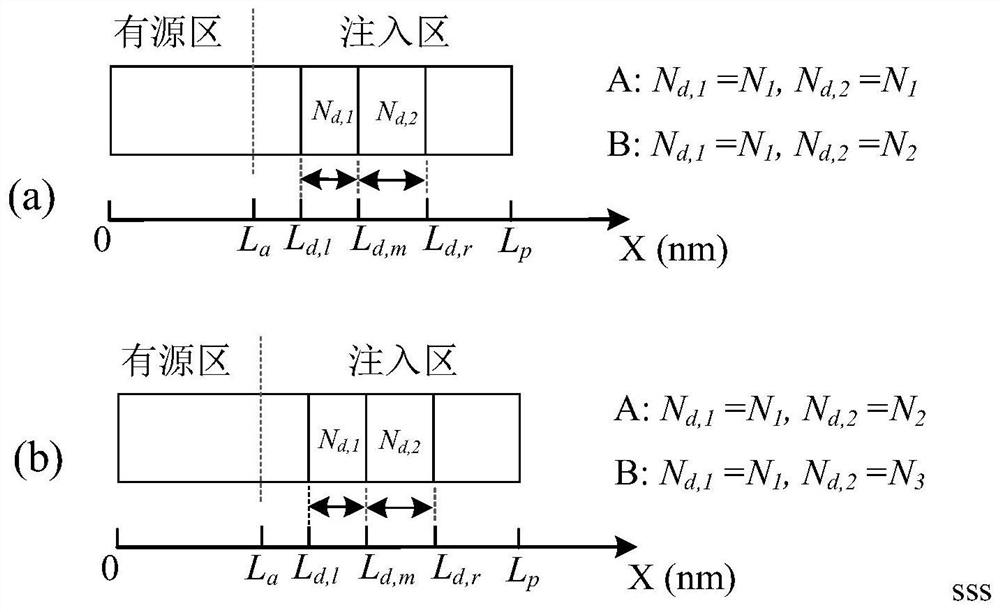
[0072] Such as image 3 As shown, in this embodiment, the QCL subunits of the quantum cascade structure layer 9 all have two doped regions. image 3 In (a), the doping concentration parameters of the two doped regions of the type A QCL subunit are the same, both being N 1 . The doping concentration parameters of the two doped regions of the B-type QCL subunit are N 1 and N 2 (N 1 ≠ N 2 ).
[0073] image 3 In (b), there are two sections of doping regions in the type A QCL subunit, and the doping concentration parameters of the two sections of doping regions are respectively N 1 and N 2 (N 1 ≠ N 2 ). Type B QCL subunits have two sections of doping regions, and the doping concentration parameters of the two sections of doping regions are respectively N 1 and N 3 (N 3 ≠ N 2 ).
[0074] same, image 3 (a) In (b), the two QCL subunits of A and B are the same on other parameters except the doping concentration parameter, where other parameters include: layer thickne...
Embodiment 3
[0076] Such as Figure 5 As shown, it is a structural schematic diagram of a three-terminal S-shaped ring quantum cascade laser of the present invention. The three-terminal S-shaped ring quantum cascade laser is sequentially arranged along the z direction from bottom to top. Substrate 7, collector 8, quantum level The structure layer 9, the quantum energy level matching layer 10, the base 11 and the emitter 12 are etched into a strip-shaped straight waveguide 18 and an S-shaped ring waveguide 19 structure. The base electrode 11 and the emitter electrode 12 are arranged in a ladder shape, and the collector electrode 8 and the quantum cascade structure layer 9 are also arranged in a ladder shape. Further, the collector electrode 8 may include a lower cladding layer, and the emitter electrode 12 may include an upper cladding layer. Specifically, the layer sequence of the device along the z direction from bottom to top is a heavy n-doped substrate 7, an n-doped collector 8, a quan...
PUM
 Abstract
Description
Claims
Application Information
 - R&D
- Intellectual Property
- Life Sciences
- Materials
- Tech Scout
- Unparalleled Data Quality
- Higher Quality Content
- 60% Fewer Hallucinations
Browse by: Latest US Patents, China's latest patents, Technical Efficacy Thesaurus, Application Domain, Technology Topic, Popular Technical Reports.
© 2025 PatSnap. All rights reserved.Legal|Privacy policy|Modern Slavery Act Transparency Statement|Sitemap|About US| Contact US: help@patsnap.com


