Laser light source and laser projection display device
A laser light source and laser technology, applied in optics, instruments, projection devices, etc., can solve the problems of thermal conductive silicone grease being easily polluted by dust and thermal conductivity of thermal conductive silicone grease, and achieve stable thermal conductivity, reduce external impact, and high luminescence efficiency effect
- Summary
- Abstract
- Description
- Claims
- Application Information
AI Technical Summary
Problems solved by technology
Method used
Image

Examples
Embodiment 1
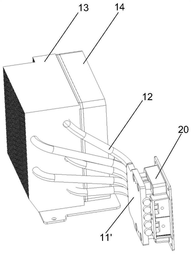
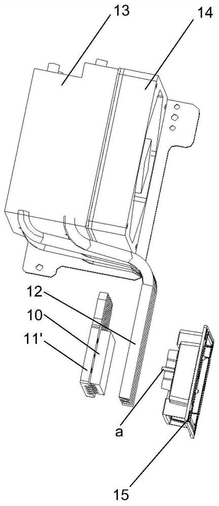
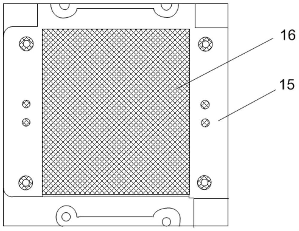
[0047] like Figure 3 to Figure 6 , Figure 12 , Figure 10 and Figure 16 As shown, an embodiment of the present invention provides a laser light source 1 . The laser light source 1 includes a heat conducting block 10 , a heat pipe assembly 12 , and a heat pipe fixing cover 11 that is fastened together with the laser housing 15 . The heat pipe fixing cover 11 and the laser housing 15 are enclosed into a receiving space. The heat pipe assembly 12 and the heat conducting block 10 are arranged in the receiving space. The surface is formed with thermally conductive material. When dissipating heat, the heat-conducting pipe absorbs the heat of the laser heat sink 16 through the heat-conducting material, and transfers the heat to the heat pipe assembly 12 , so that the heat pipe assembly 12 conducts the heat out.
[0048]Based on the structure and heat dissipation process of the above-mentioned laser light source 1, it can be known that the above-mentioned heat pipe fixing cover...
Embodiment 2
[0080] like Figure 16 As shown, the present invention also provides a laser projection display device, the laser projection display device includes a laser light source 1, an optical machine 2 and a lens 3, and the laser light source is the laser light source described in the first embodiment.
[0081] Figure 16 The arrows shown represent the light path diagram of the laser light emitted by the laser light source. Among them, the laser light source 1 is used to provide laser light to the optical machine 2; the optical machine 2 is used to modulate the laser light, and project the modulated laser light to the lens 3, so that the modulated laser light is imaged through the lens, that is, the lens will The modulated laser light is projected onto the screen, so that the modulated laser light is imaged.
[0082] Compared with the prior art, the beneficial effects of the laser projection display device provided by the embodiment of the present invention are the same as the benef...
Embodiment 3
[0085] Using thermal simulation software simulation simulation method to design such as Image 6 and Figure 7 Raised structures 112 are shown and as Figure 11 and Figure 12 The dustproof structure formed by the limiting structure 150 is shown, and the influence of the dustproof structure on the temperature Tm of the laser heat sink is simulated.
[0086] The simulation parameters are: the power of the laser is set to 150W, the speed of the fan is set to 1000RPM, 150RPM, 2000RPM, and 3000RPM, and the ambient temperature is 25°C. Radiation heat transfer was ignored in the simulation, and the thermal conductivity of the heat pipe was set to 20000 W / m·K. When forming the grid, the level of thermal blocks and heat pipes is set to 4level. Compare the laser heat sink temperature Tm with or without the dust-proof structure. The results are shown in Table 1.
[0087] Table 1 Temperature variation of laser heat sink under different simulation parameters
[0088]
[0089] Ac...
PUM
| Property | Measurement | Unit |
|---|---|---|
| thermal conductivity | aaaaa | aaaaa |
Abstract
Description
Claims
Application Information
 - R&D
- Intellectual Property
- Life Sciences
- Materials
- Tech Scout
- Unparalleled Data Quality
- Higher Quality Content
- 60% Fewer Hallucinations
Browse by: Latest US Patents, China's latest patents, Technical Efficacy Thesaurus, Application Domain, Technology Topic, Popular Technical Reports.
© 2025 PatSnap. All rights reserved.Legal|Privacy policy|Modern Slavery Act Transparency Statement|Sitemap|About US| Contact US: help@patsnap.com