
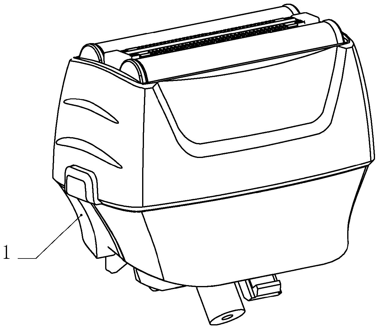
Cutting head device and shaver

A cutter head and integrated technology, applied in the field of cutter head device and razor, cutter head device, can solve the problems of increasing the noise of the cutter head, unfavorable production and assembly, and increasing the noise of the shaver, so as to reduce the temperature rise and vibration intensity , Improve the comfort of use, improve the effect of shaving comfort

Pending Publication Date: 2020-07-24
浙江海顺电工有限公司
View PDF1 Cites 0 Cited by
  • Summary
  • Abstract
  • Description
  • Claims
  • Application Information

AI Technical Summary

Problems solved by technology

[0002] The applicant applied for an invention patent named a shaver and its cutter head device on May 10, 2012. The announcement number is CN 102642213 B. This patent document actually solves the technology of reverse reciprocating motion of double cutter heads. problem, but in the production and use of the cutter head, there are also some technical defects, specifically as follows: first, the rotating part is hinged and fixed on the fixed frame by means of the third hinge shaft arranged on the fixed frame, while the fixed The frame uses the card slot provided in the shell, and the structure is relatively complicated, which is not conducive to production assembly and increases the production cost
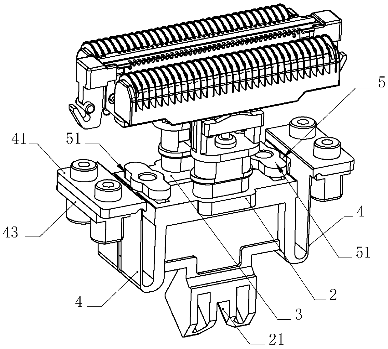
Its two, fixed frame is installed and fixed between the first swing frame and the second swing frame, although it can facilitate the hinged fixing of the rotating part like this, and it is beneficial to the first hinged hole and the second hinged hole at the two ends of the rotating part to be connected with the first hinged hole respectively. The hinge shaft and the second hinge shaft are hinged to make the two swing frames produce reverse reciprocating motion, but in actual use, the first swing frame and the second swing frame constantly rub against the fixed frame when swinging in reverse. , which greatly increases the noise of the cutter head and reduces the comfort of the shaver
Third, the first swing frame, the fixed frame and the second swing frame are all engaged with the bending grooves in the housing through the bending parts arranged at both ends. Although this engaging structure is easy to assemble, it is firmly installed. The accuracy is poor, and it is fixed by splicing the left and right shells. In the process of assembly and use, affected by processing accuracy or external factors, the first swing frame, the fixed frame and the second swing frame are prone to misalignment or vibration displacement. , while improving the noise of the shaver, it also affects the safety of the cutter head device

Method used


Image

  • Cutting head device and shaver
  • Cutting head device and shaver
  • Cutting head device and shaver

Examples


Embodiment 1

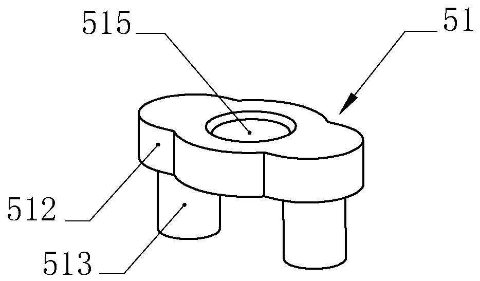
[0039] Such as Figure 2-9 As shown, in order to facilitate the horizontal reciprocating swing of the first swing frame 2 under the drive of the driving parts, the second swing frame 3 can be synchronized with the first swing frame 2 to swing in the opposite direction, and the movement of the two swing frames in opposite directions To buffer the kinetic energy inertia caused by the swing, reduce the vibration amplitude of the cutter head, and reduce the vibration intensity of the cutter head. The transmission member 5 includes two first linkages 51, two first linkages 51 are arranged, and are installed on the two ends of the first swing frame 2 and the second swing frame 3 respectively, when the first swing frame 2 When the driving part is driven to reciprocate horizontally, the second pendulum frame 3 can also move synchronously and reversely under the drive of the two first linkages 51, and in the process of reverse swinging, it is affected by the two first linkages. The li...

Embodiment 2

[0042] Such as Figure 10-16 As shown, the inventor has also proposed a transmission structure different from that of Embodiment 1. This transmission structure can not only ensure the reverse reciprocating motion of the double cutter head, but also ensure the first pendulum frame 2 and the second pendulum at the same time. To swing the frame 3 at intervals in parallel, the technical solution adopted is: the transmission member 5 includes a second linkage member 52, a third linkage member 53 and a fourth linkage member, and the third linkage member 53 and the fourth linkage member are the same Both are composed of two guide shafts 531 and guide grooves 532 matched with the guide shafts 531; the guide grooves 532 are respectively arranged at both ends of the first swing frame 2 and the second swing frame 3, and the direction of the guide grooves 532 is the same as that of the first swing frame. The swing directions of the frame 2 and the second swing frame 3 are consistent, the ...


PUM


Abstract

The invention relates to a cutting head device, which is characterized in that the elastic bending parts of the first swing frame and the second swing frame are connected as one body, so that the first swing frame and the second swing frame are fixed in a housing in parallel and spaced apart; the housing is also provided with a plurality of transmission parts that make the first swing frame and the second swing frame move in parallel and opposite directions; and each transmission part is fixedly connected with the housing. The beneficial effect of the present invention is that the elastic bending parts of the first swing frame and the second swing frame are fixedly connected into one body. During the assembly or working process, the device can effectively avoid assembly misalignment or vibration displacement, reduce the amplitude, and reduce The vibration intensity improves the shave comfort of the cutter head; and a plurality of transmission parts are arranged between the first swingframe and the second swing frame, which can prevent the force transmission direction of the external driving component from changing and cause the first swing frame and the second swing frame to change. The two swing frames cannot achieve parallel swing, so that the shaving performance of the double heads is improved, and the temperature rise and vibration intensity, and the comfort of the shaverare improved.

Description

technical field [0001] The invention relates to a cutter head device, more specifically to a cutter head device and a shaver, and is mainly used in the field of shaver. Background technique [0002] The applicant applied for an invention patent named a shaver and its cutter head device on May 10, 2012. The announcement number is CN 102642213 B. This patent document actually solves the technology of reverse reciprocating motion of double cutter heads. problem, but in the production and use of the cutter head, there are also some technical defects, specifically as follows: first, the rotating part is hinged and fixed on the fixed frame by means of the third hinge shaft arranged on the fixed frame, while the fixed The frame utilizes the card slot provided in the housing, and has a relatively complex structure, which is not conducive to production assembly and increases production cost. Its two, fixed frame is installed and fixed between the first swing frame and the second swi...

Claims


Application Information

Patent Timeline
Patent Type & Authority Applications(China)
IPC IPC(8): B26B19/02B26B19/04
CPCB26B19/02B26B19/04
Inventor 钟海勇
Owner 浙江海顺电工有限公司
Learn More