
Guide mechanism of drainage valve shell

A technology of drainage valve and guide structure, which is applied in the field of bathroom, can solve the problems affecting the guide performance of guide tubes, and achieve the effect of high product guide precision

Active Publication Date: 2014-03-12
BESTTER XIAMEN TECH
View PDF5 Cites 0 Cited by
  • Summary
  • Abstract
  • Description
  • Claims
  • Application Information

AI Technical Summary

Problems solved by technology

Since the guide of the conduit is on the body and the bottom plate, if the assembly of the body and the bottom plate is misaligned or there is a dimensional deviation, the guiding performance of the conduit will be affected

Method used


Image

  • Guide mechanism of drainage valve shell
  • Guide mechanism of drainage valve shell
  • Guide mechanism of drainage valve shell

Examples


Embodiment Construction

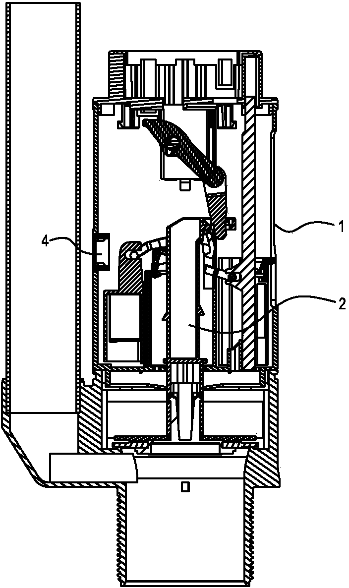
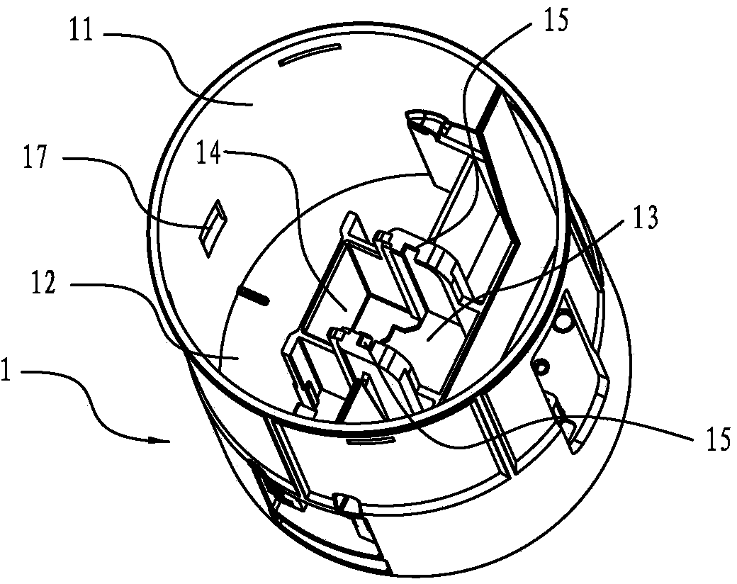
[0032] For specific embodiments of the present invention, refer to Figure 1 to Figure 4 A casing 1 of a drain valve is a cylindrical shape with one end closed, and it includes a cylindrical wall 11 and a bottom plate 12 at the lower end.

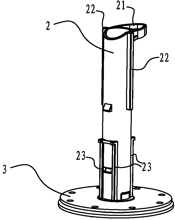
[0033] A central guide hole 13 is provided at the center of the bottom plate 11 . Around the central guide hole 13, a square surrounding wall 14 is provided upwards, and the bottom plate 12 and the surrounding wall 14 are integrally formed. The bottom plate and the cylinder wall are independent parts respectively. Wherein, the two sides of central guide hole 13, the inner upper end of surrounding wall 14 are symmetrically provided with a pair of guide grooves 15 in the vertical direction, wherein, the guide position of central guide hole 13 is 13-1 (that is, cooperates with the guide rib 23 of the conduit. position), the guide groove 15 and the guide position 13-1 do not coincide on the vertical projection.

[0034] A through hole 17 is ...


PUM


Abstract

The invention discloses a guide mechanism of a drainage valve shell. The shell is cylindrical, one end of the shell is sealed, the shell comprises a cylindrical wall and a bottom plate located at the lower end, the center of the bottom plate is provided with a center guide hole allowing a guide pipe to pass, a surrounding wall is upwards arranged around the periphery of the center guide hole, and the bottom plate and the cylindrical wall are integrally formed. The inner side of the surrounding wall is provided with a guide groove matched with the guide pipe, and the guide portion of the guide hole and the guide groove are staggered on a vertical projection. Due to the fact that the surrounding wall of the shell and the bottom plate are integrally formed, so that the dislocation which may happen due to dimensional tolerance after two parts are assembled is avoided, and guide precision is high.

Description

technical field [0001] The invention relates to the field of sanitary ware, in particular to a guide mechanism for a housing of a drain valve. Background technique [0002] The flush toilet that hotel, family all use mostly now, a water inlet valve and a discharge valve are installed in the water tank of toilet. [0003] The existing drain valve includes a body, and an upper cover is installed in the main body, and a guide hole is arranged in the center of the upper cover. The bottom of the body is provided with a film, and the center of the film is also provided with a guide hole. The conduits pass through the guide holes of the upper cover and the film respectively. The upper end of the conduit is connected to the hook, and the lower end of the conduit is connected to the silicone cover to seal water or drain. Since the conduit is guided on the body and the base plate, if the body and the base plate are misaligned or have dimensional deviations, the guiding performance of...

Claims


Application Information

Patent Timeline
Patent Type & Authority Applications(China)
IPC IPC(8): E03D1/34E03D1/35
Inventor 黄永泉陈俊生龚斌华
Owner BESTTER XIAMEN TECH
Learn More