Rotatable medical instrument disinfection device
A technology for disinfection devices and medical devices, applied in disinfection, water supply devices, buildings, etc., can solve the problems of incomplete disinfection, inaccessibility of disinfectant solution, waste of disinfectant solution, etc., and achieve better disinfection effect and better spraying effect Effect
- Summary
- Abstract
- Description
- Claims
- Application Information
AI Technical Summary
Problems solved by technology
Method used
Image
Examples
specific Embodiment approach 1
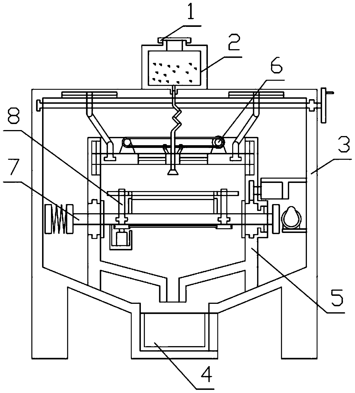
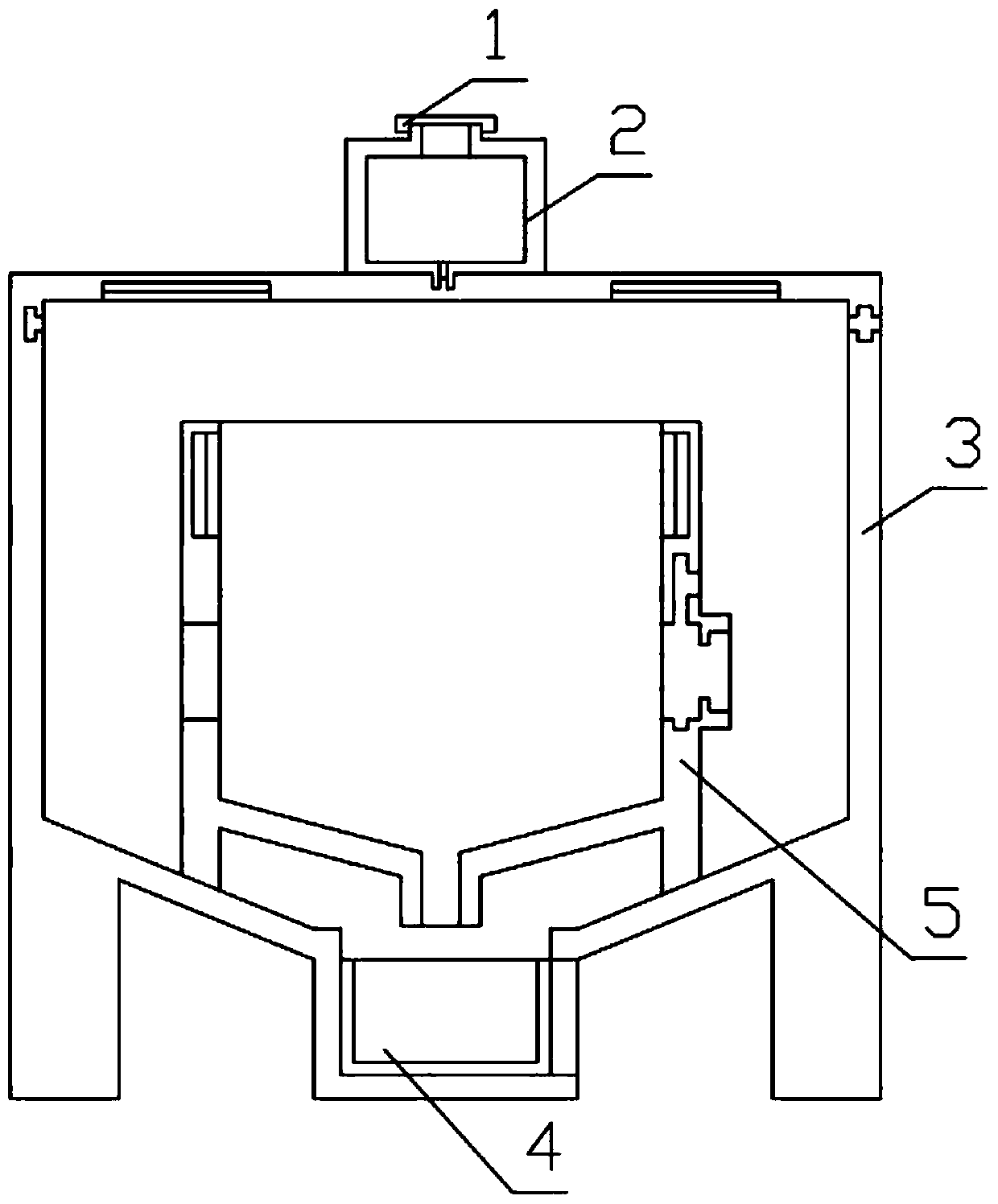
[0029] Combine below Figure 1-9 Describe this embodiment, a rotatable medical device disinfection device, including a box cover 1, a disinfectant tank 2, a device shell 3, a disinfectant collection box 4 and an inner box 5 of the device, the box cover 1 and the disinfectant tank 2 are threaded, The disinfectant solution box 2 is installed on the device shell 3, the disinfectant solution collection box 4 is installed on the device shell 3, the device inner box 5 is fixedly installed in the inside of the device shell 3, the device shell 3 is equipped with a door, and the device inner box 5 is installed There is a door, and a pressure device is arranged on the disinfectant tank 2. The adjustable spraying mechanism 6 is installed on the device shell 3, the adjustable spraying mechanism 6 is slidably installed on the inner box 5 of the device, and the appliance balance mechanism 7 is installed on the device. On the inner box 5, the utensil fixing mechanism 8 is installed on the ut...
specific Embodiment approach 2
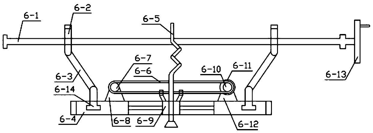
[0031] Combine below Figure 1-9Describe this embodiment, this embodiment will further explain the first embodiment, the adjustable spraying mechanism 6 includes a two-way threaded rod 6-1, a threaded moving part 6-2, a swinging part 6-3, a sliding plate 6-4, Hose with nozzle 6-5, belt 6-6, pulley 1 6-7, mounting seat 6-8, hose sliding seat 6-9, pulley 2 6-10, pulley motor 6-11, motor Base 6-12, hand plate 6-13, hinge 6-14, one end of two-way threaded rod 6-1 is installed on the groove provided on device shell 3, and the other end of two-way threaded rod 6-1 is rotated and installed On the through hole provided on the device shell 3, the two-way threaded rod 6-1 is fixedly connected with the hand pan 6-13, the threaded moving part 6-2 is threadedly connected with the two-way threaded rod 6-1, and the threaded moving part 6-2 slides Installed on the groove provided on the device shell 3, the threaded moving part 6-2 is hinged with the swinging part 6-3, the swinging part 6-3 i...
specific Embodiment approach 3
[0033] Combine below Figure 1-9 This embodiment will be described. This embodiment will further describe Embodiment 1. The appliance balance mechanism 7 includes a buffer plate 7-1, a buffer spring 7-2, a connecting plate 7-3, a bottom grille 7-4, and a side Baffle plate 7-5, special-shaped rotating part 7-6, top backing plate 7-7, cam 7-8, connection base 7-9, cam motor 7-10, T-shaped mounting seat 7-11, rotation motor 7- 12. The rotating gear 7-13, the rubber sheet 7-14, the buffer plate 7-1 are fixedly connected with the buffer spring 7-2, the buffer spring 7-2 is fixedly connected with the connecting plate 7-3, and the connecting plate 7-3 is connected with the bottom lattice The plate 7-4 is fixedly connected, the bottom grid plate 7-4 is slidably installed on the through hole provided on the side baffle plate 7-5, the rubber sheet 7-14 is fixedly installed on the inner box 5 of the device, and the bottom grid plate 7-4 is connected with the The side baffle 7-5 is fixed...
PUM
 Abstract
Description
Claims
Application Information
 - Generate Ideas
- Intellectual Property
- Life Sciences
- Materials
- Tech Scout
- Unparalleled Data Quality
- Higher Quality Content
- 60% Fewer Hallucinations
Browse by: Latest US Patents, China's latest patents, Technical Efficacy Thesaurus, Application Domain, Technology Topic, Popular Technical Reports.
© 2025 PatSnap. All rights reserved.Legal|Privacy policy|Modern Slavery Act Transparency Statement|Sitemap|About US| Contact US: help@patsnap.com


