
Industrial robot and method for operating industrial robot

A technology of industrial robots and controllers, which is applied to the device for coating liquid on the surface, coating, and pretreatment of the surface, etc., which can solve the problems of low processing efficiency of parts, affecting the processing process, and poor spraying effect, so as to improve processing efficiency , improve fluidity, spray uniform effect

Pending Publication Date: 2022-04-26
NANTONG VOCATIONAL COLLEGE
View PDF5 Cites 2 Cited by
  • Summary
  • Abstract
  • Description
  • Claims
  • Application Information

AI Technical Summary

Problems solved by technology

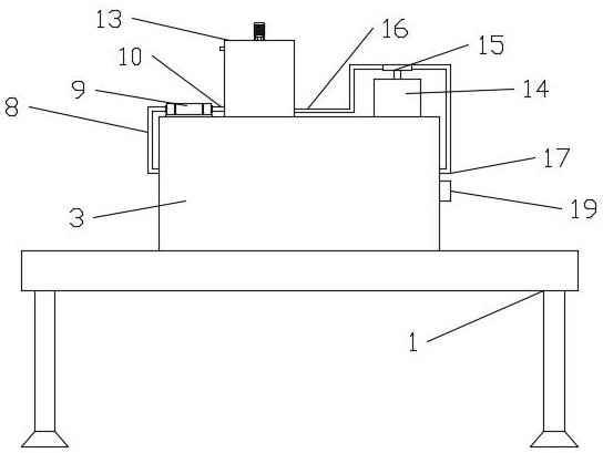
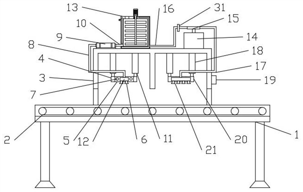
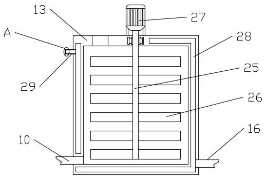
[0005] To this end, the present invention provides an industrial robot and a method for operating the industrial robot. The paint in the material box is transported to the leveling chamber through a pumping component, and the reciprocating component drives the spraying to reciprocate in the horizontal direction to realize spraying. Spray the paint evenly on the parts, the spraying is more uniform, and the spraying effect is good. It is equipped with a heating component and an air spraying component. The processing efficiency is high, and the heating component can transport the hot air into the air cavity to heat the paint properly, and the stirring component can stir the paint, which can improve the fluidity of the paint, thereby improving the spraying effect of the parts, so as to solve the problem currently used Spraying industrial robots have poor spraying effect on parts, and do not have the ability to dry the sprayed parts, resulting in slow drying of the paint on the parts, which affects the subsequent processing process, resulting in low processing efficiency of the parts.

Method used


Image

  • Industrial robot and method for operating industrial robot
  • Industrial robot and method for operating industrial robot
  • Industrial robot and method for operating industrial robot

Examples


Embodiment Construction

[0028] The preferred embodiments of the present invention will be described below in conjunction with the accompanying drawings. It should be understood that the preferred embodiments described here are only used to illustrate and explain the present invention, and are not intended to limit the present invention.

[0029] Refer to attached Figure 1-6 , a kind of industrial robot that the present invention provides, comprises installation platform 1, is provided with conveyer belt 2 in the top of installation platform 1, is fixedly installed with spraying box 3 above the middle part of installation platform 1, also includes spraying and controller 19, and spraying mechanism is fixed Installed in one side of the spraying box 3, the spraying mechanism is fixedly connected with a feeding mechanism, the side of the spraying box 3 away from the spraying mechanism is fixedly installed with an air spray assembly, the air spray assembly is fixedly connected with a heating assembly, and...


PUM


Abstract

The invention relates to the technical field of industrial robots, in particular to an industrial robot and a method for operating the industrial robot, and adopts the technical scheme that the industrial robot comprises a mounting table, a conveying belt is arranged in the top end of the mounting table, a spraying box is fixedly mounted above the middle of the mounting table, and the industrial robot further comprises a spraying device and a controller; the spraying mechanism is fixedly installed in one side of the spraying box, the spraying mechanism is fixedly communicated with a feeding mechanism, an air injection assembly is fixedly installed in the side, away from the spraying mechanism, of the spraying box, the air injection assembly is fixedly communicated with a heating assembly, the controller is fixedly installed on one side of the spraying box, and the controller is electrically connected with the conveying belt. According to the paint spraying device, paint can be evenly sprayed to parts through the spray head, spraying is more uniform, the spraying effect is good, hot air is sprayed to the parts through the air spraying assembly, the paint on the parts is rapidly dried, and then the machining efficiency of the parts is improved.

Description

technical field [0001] The invention relates to the technical field of industrial robots, in particular to an industrial robot and a method for operating the industrial robot. Background technique [0002] At present, with the development of society, people's living standards continue to improve, and various new products have entered people's lives one after another. With the development of economy, my country has gradually transitioned from the era of low labor costs to the era of high costs. , due to the increase in labor costs, the use cost of enterprises has also increased greatly. In the face of fierce competition, enterprises have to consider reducing labor costs. Therefore, it has become an inevitable trend to use industrial robots instead of labor. Industrial robots are a kind of automation degree and work High-efficiency automation equipment, its work is controlled by a preset program, and the same action is fixedly completed. These industrial robots are widely used i...

Claims


Application Information

Patent Timeline
IPC IPC(8): B05B13/02B05B13/04B05B9/00B05B15/25B05B16/20B05D3/04
CPCB05B13/0221B05B13/041B05B9/002B05B15/25B05B16/20B05D3/0413
Inventor 王凌施宏王丁丁
Owner NANTONG VOCATIONAL COLLEGE
Learn More