Oil fume buffer mechanism for range hood

The technology of a range hood and a buffer mechanism is applied in the direction of removing oil fume, applications, and household stoves. Smoke resistance, noise reduction effect

Active Publication Date: 2022-06-21
NINGBO FOTILE KITCHEN WARE CO LTD
View PDF8 Cites 0 Cited by
  • Summary
  • Abstract
  • Description
  • Claims
  • Application Information

AI Technical Summary

Problems solved by technology

[0004] Once there is a gap between the valve plate and the valve body, when the pressure in the public flue is high and the floor of the user is high, the oil fume in the public flue will enter the smoke pipe of the indoor range hood through the gap, forming a non-working state of the hood. The oil fume is poured backwards, producing kitchen oil fume and peculiar smell; at the same time, when the range hood is in normal working condition, the oil fume resistance in the public flue will be relatively large, that is, when the pressure of the oil fume in the public flue is greater than the pressure in the smoke pipe, at this time, the range hood The smoke exhaust is blocked, and at the same time, it is very easy to cause the oil fume to flow backward, and the situation of the smoke exhaust is more serious during the use of the range hood during the peak period. In addition, the smoke exhausted by the range hood and the oil fume poured back form a vortex in the smoke pipe. As a result, the noise in the smoke pipe increases, and at the same time, the valve plate is prone to unstable swing, which affects the exhaust of oil fume during the peak period, and increases the smoke exhaust resistance and noise.

Method used


Image

  • Oil fume buffer mechanism for range hood
  • Oil fume buffer mechanism for range hood
  • Oil fume buffer mechanism for range hood

Examples


Embodiment 1

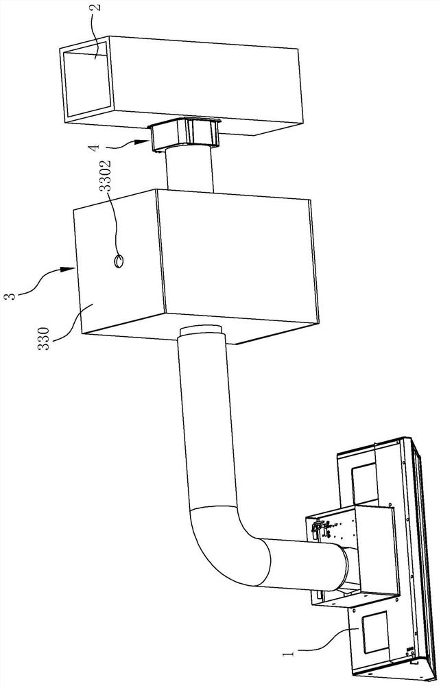
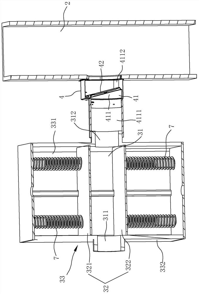
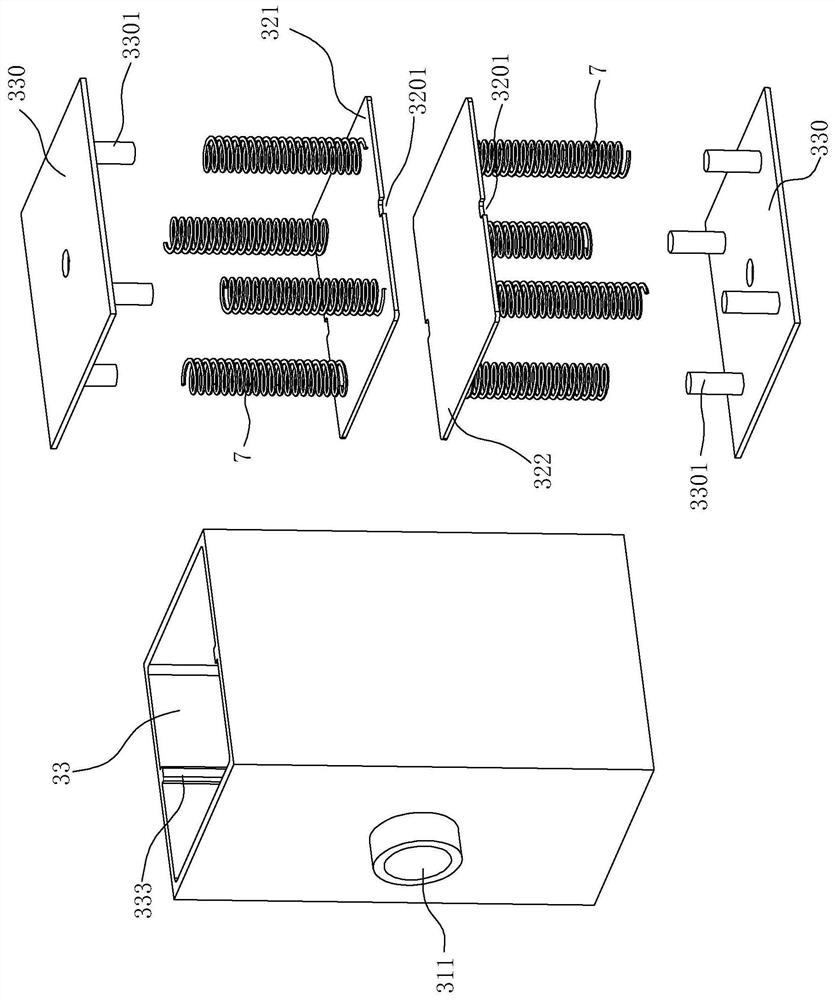
[0051] like Figure 1 to Figure 3 shown, is the first preferred embodiment of the invention. The oil fume buffer mechanism for a range hood in this embodiment includes a check valve 4 and an oil fume buffer device 3 .

[0052] The check valve 4 of this embodiment includes a valve body 41 and a valve plate 42 , wherein the valve body 41 is provided with a connecting frame 43 and a rotating shaft 44 that can rotate around its own axis, and the first end of the connecting frame 43 is opposite to the rotating shaft 44 Fixed, the second end of the connecting frame 43 is relatively fixed with the valve plate 42, that is, the valve plate 42, the connecting frame 43 and the rotating shaft 44 rotate synchronously. The air inlet 4111 which is in fluid communication with the air outlet of the hood 1 and the air outlet 4112 which is used for fluid communication with the common flue 2, the valve plate 42 is arranged on the smoke exhaust channel 411 and can be rotated relative to the valve...

Embodiment 2

[0059] like Figure 4 and Figure 5 shown, is a second embodiment of the present invention. The only difference between this embodiment and the above-mentioned first embodiment is that the buffer device 3a is different. The buffer device 3a is provided with a first driving mechanism for driving the first movable plate 321a and the second movable plate 322a to slide in and out in the lateral direction.

[0060] The above-mentioned first driving mechanism includes a motor 61a and a first transmission member, the power output end of the motor is connected with the first transmission member, and the power output end of the first transmission member acts on the first movable plate 321a and the second movable plate 322a. . The first transmission member in this embodiment includes a first rack 63a and a second rack 64a, the auxiliary cavity 33a includes a first auxiliary cavity 331a and a second auxiliary cavity 332a, and the inner peripheral wall of the first auxiliary cavity 331a...

Embodiment 3

[0066] like Figures 6 to 8 shown, is a third embodiment of the present invention. The only difference between this embodiment and the second embodiment above is that the transmission parts of the driving mechanism are different. Specifically, the driving mechanism includes a motor 61b and a first transmission part, and the power output end of the motor 61b is connected to the power output of the first transmission part. The ends are connected, and the power output end of the first transmission member acts on the first movable plate 321b and the second movable plate 322b. The first transmission member is a screw 62b, the screw 62b extends along the lateral direction of the main oil fume channel 31b, and the screw 62b has a first thread segment 621b and a second thread segment 622b. The rotation directions of the threads on the two threaded segments 622b are opposite, the first movable plate 321b is provided with a first screw hole 3211b that cooperates with the first threaded...


PUM


Abstract

The invention relates to an oil fume buffer mechanism for a range hood, which includes a check valve and an oil fume buffer device. The valve body of the check valve has a smoke exhaust channel, and the smoke exhaust channel has an air inlet and an air outlet. The valve plate is set on the smoke exhaust channel, and can be rotated relative to the valve body to open or block the smoke exhaust channel; the oil fume buffer device is arranged between the air outlet and the air inlet of the valve body, which has a main oil smoke channel, and the main oil smoke channel There are connected smoke inlet and smoke outlet in the longitudinal direction, the smoke inlet is in fluid communication with the air outlet, and the smoke exhaust is in fluid communication with the air inlet; the partial side wall of the main oil fume channel has at least one laterally outward expansion The main structure that increases the volume of the main oil fume passage. When the oil fume is poured back through the gap of the check valve, when the main structure is subjected to the pressure in the main oil fume channel, the volume increases to slow down the pressure of the oil fume in the main oil fume channel, and temporarily stores the oil fume, which delays the oil fume from flowing back through the range hood to a certain extent Go indoors.

Description

technical field [0001] The invention relates to the technical field of range hoods, in particular to an oil fume buffer mechanism for range hoods. Background technique [0002] At present, the exhaust fume outlets of the kitchens of the residents of the building are connected to a fume exhaust channel that runs through the upper and lower sides. In order to prevent the oil fume in the flue gas duct from flowing back into the kitchen, an exhaust pipe is installed between the exhaust pipe of the range hood and the public flue. There are devices like flue check valves. [0003] The existing flue check valve generally includes an oil fume channel formed by a casing, the oil fume channel has an opposite air inlet and an air outlet, the air inlet is connected to the air outlet of the range hood, and the air outlet extends into the common flue gas duct. , There is a valve plate that can be opened and closed at the air outlet of the fume channel. The check valve is a one-way valve,...

Claims


Application Information

Patent Timeline
Patent Type & Authority Patents(China)
IPC IPC(8): F24C15/20
CPCF24C15/20
Inventor 杨历
Owner NINGBO FOTILE KITCHEN WARE CO LTD
Why Eureka
Try Eureka