Microwave oven with convection heating

a convection heating and microwave oven technology, applied in the field of microwave ovens, can solve the problems of uneven heating, overheating or drying of foodstuffs or portions thereof in the vicinity, and low air flow, so as to reduce the whirl of air injected, improve the flow of heated air, and prevent microwave energy.

Active Publication Date: 2005-03-10
WHIRLPOOL CORP
View PDF5 Cites 14 Cited by
  • Summary
  • Abstract
  • Description
  • Claims
  • Application Information

AI Technical Summary

Benefits of technology

[0009] The present invention attempts to improve flow of heated air into a cooking cavity of an appliance by providing the appliance with comparatively large openings in the rear wall of the cavity, and to have air conduits connected to these openings. It is believed that these air conduits have three primary functions, namely to prevent microwave energy from escaping out of the cooking cavity, to guide hot air in a desired manner, and to reduce the whirl of the air injected into the cooking cavity.

Problems solved by technology

However, these perforations have the potential to cause an obstacle for the circulating air, leading to a lower flow of air than what is desired.
To overcome this, the air flow (fan speed) or the air temperature must be increased, which unfortunately may lead to over-heating or drying of foodstuffs or portions thereof in the vicinity of the inlet perforations.
As a result, due to the whirl, the hot air might not reach all parts of the cooking cavity, which could result in uneven heating.

Method used


Image

  • Microwave oven with convection heating
  • Microwave oven with convection heating
  • Microwave oven with convection heating

Examples


example 1

[0032]

ConduitLength, LWidth, WHeight, HAngle, α26A60 mm26 mm10 mm45°26B60 mm26 mm26 mm45°26C60 mm26 mm26 mm45°26D60 mm26 mm 8 mm60°

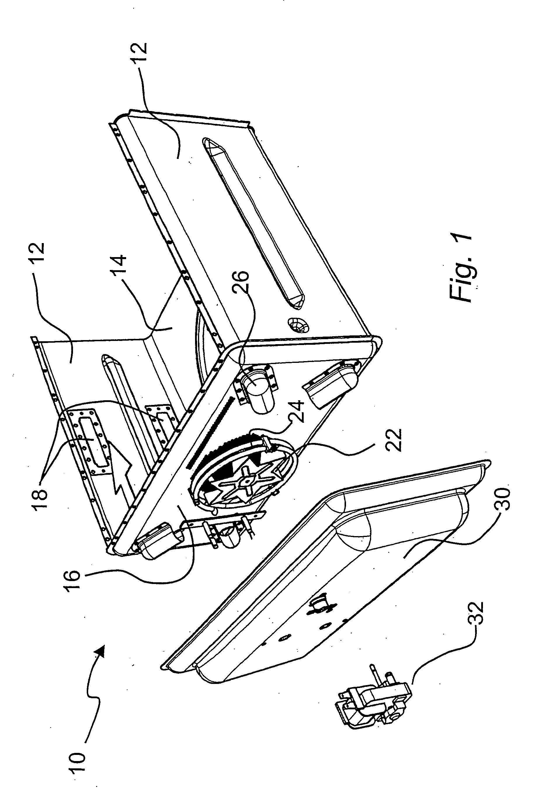
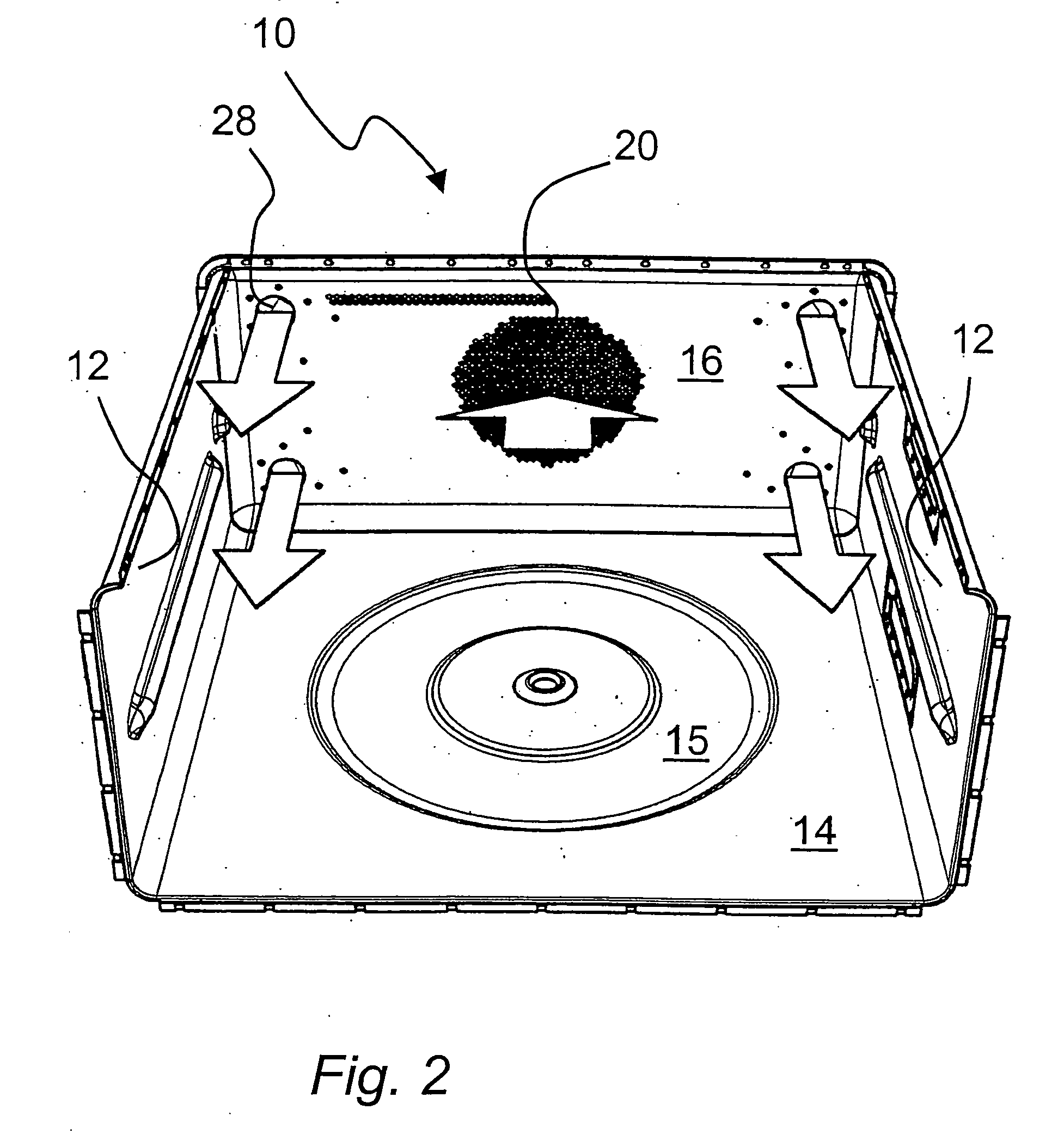
[0033] In Example 1, the upper conduits A and D have a smaller height than the lower conduits in order to provide a larger airflow at the bottom of the cooking cavity. To some degree, the whirl produced by the fan is reduced when the air flows through the conduits. However, the final reduction of whirl is obtained by mounting conduit D at a larger angle than the other conduits.

example 2

[0034]

ConduitLength, LWidth, WHeight, HAngle, α26A60 mm26 mm26 mm45°26B60 mm26 mm26 mm45°26C60 mm26 mm26 mm45°26D60 mm26 mm26 mm72°

[0035] In Example 2, all the conduits have about the same dimensions. Hence, only one type of conduit member is required for this embodiment. Still, a desired flow of hot air in the cooking cavity can be obtained. In this example, conduit D is again mounted at a larger angle than the other conduits, in order to provide the final reduction of whirl and obtain the desired heating evenness in the cooking cavity.

[0036] In both examples above, the diameter of each of the injection openings is equal to the width of the conduits, i.e. about 26 mm.

[0037] Having read and understood this description, the person of ordinary skill in the art will find a number of different configurations for the injection openings and the air conduits that fall within the scope of the present invention.

[0038] For example, it will be understood by the skilled person that the injec...


PUM


Abstract

A combined microwave and hot-air circulating cooking appliance is disclosed. The appliance has a plurality of air injection openings that are provided in a wall of the cooking cavity for injecting heated air into the same. Each of the injection openings is connected to a heating compartment an air conduit having such dimensions so as to prevent propagation of microwave energy through the conduit.

Description

BACKGROUND OF THE INVENTION [0001] 1. Field of the Invention [0002] The present invention relates to microwave ovens with a capability of convection heating by circulation of hot air within the microwave cavity. [0003] 2. Description of the Related Art [0004] Cooking appliances arranged for both microwave heating and convection heating by hot-air circulation are known. Such appliances can generally operate in microwave mode, where microwave heating is effected, or in convection mode, where heating by hot-air circulation is effected. It is also possible to use a combination of the two modes, in which microwaves assist the hot-air heating process. [0005] In a fan-assisted convection heating oven, it is generally desired to have a uniform distribution of hot air within the cooking chamber in order to promote even heating of foodstuff placed therein. Typically, a heater and a fan are placed behind the rear wall of the microwave cooking cavity in a dedicated compartment. Air is drawn by ...

Claims


Application Information

Patent Timeline
Patent Type & Authority Applications(United States)
IPC IPC(8): H05B6/80
CPCH05B6/6476
Inventor EKINGE, ROLANDNYREN, GUNNARGARCIA-PADRON, RICARDO
Owner WHIRLPOOL CORP
Why Eureka
Try Eureka