
Data transmission method and device

A data transmission method and equipment technology, applied in the field of communication, can solve problems such as ActiveDLBWP change of terminal equipment, logical channel business freeze, terminal equipment unable to receive downlink data, etc., to achieve the effect of reducing negative impact and improving business continuity

Active Publication Date: 2020-07-17
HUAWEI TECH CO LTD
View PDF11 Cites 3 Cited by
  • Summary
  • Abstract
  • Description
  • Claims
  • Application Information

AI Technical Summary

Problems solved by technology

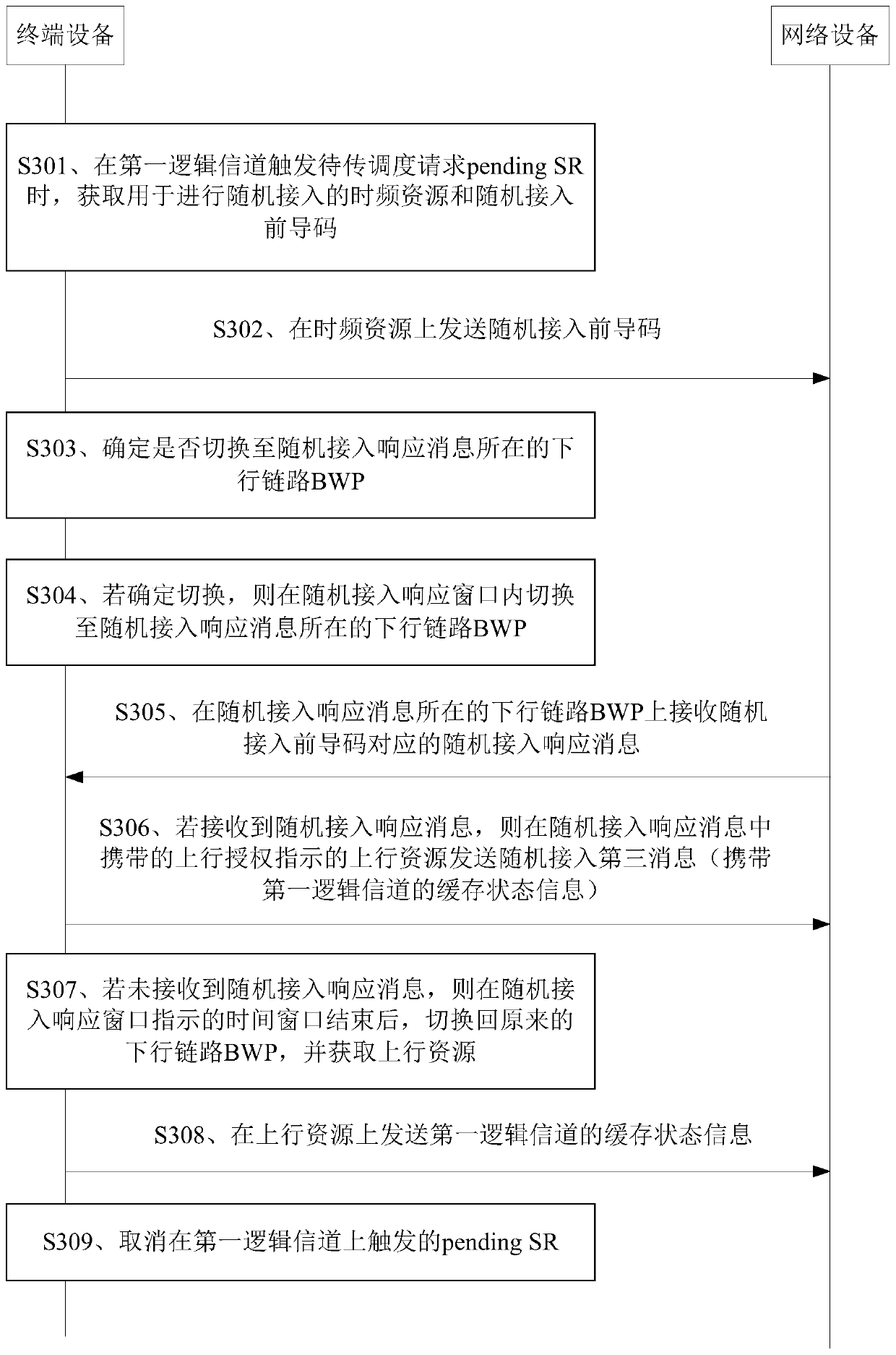
If the currently activated Active UL bandwidth part (Bandwidth Part, BWP) is not configured with a Physical Random Access Channel (Physical Random Access Channel, PRACH) PRACH resource, the terminal device will switch to the initial Initial UplinkBWP for random access, and It will switch the Active downlink (Downlink DL) BWP to Initial DownlinkBWP, causing the DL BWP on the terminal device side to change; if the current Active UL BWP is configured with PRACH resources, the terminal device will switch the Active DL BWP to the same as the Active UL BWP On the DL BWP with the same BWP ID, in a Frequency Division Duplex (FDD) system, since the Active DL BWP ID is not necessarily the same as the Active UL BWP ID, the Active DL BWP of the terminal device may change
[0004] Therefore, if the terminal device switches the current Active DLBWP after sending the random access preamble Preamble, when the service corresponding to a logical channel generates downlink data, the network device will continue to send the downlink on the Active DL BWP before the terminal device switches At this time, because the Active DL BWP of the terminal device has changed, the terminal device cannot receive the downlink data, resulting in a freeze or interruption of the service on the logical channel

Method used


Image

  • Data transmission method and device
  • Data transmission method and device
  • Data transmission method and device

Examples


Embodiment Construction

[0093] The technical solutions in the present application will be described below with reference to the accompanying drawings.

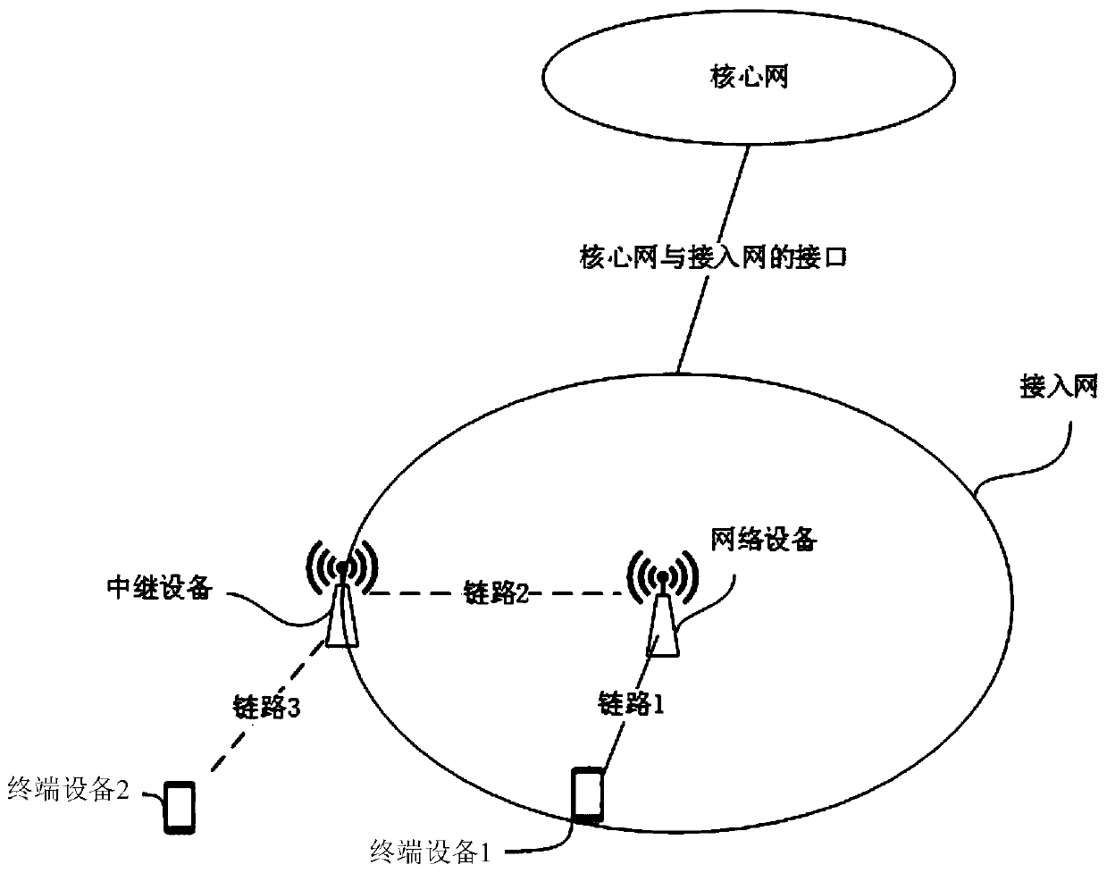
[0094] It should be understood that the technical solutions in the embodiments of the present application may be applied to a New Radio (New Radio, NR) system or a Long Term Evolution (Long Term Evolution, LTE) architecture, and may also be applied to a Universal Mobile Telecommunications System (Universal Mobile Telecommunications System, UMTS) terrestrial Radio Access Network (UMTS Terrestrial Radio Access Network, UTRAN) architecture, or Global System for Mobile Communication (Global System for Mobile Communication, GSM) / Enhanced Data Rate for GSM Evolution (Enhanced Data Rate for GSMEvolution, EDGE) system radio access network ( GSM EDGE Radio Access Network, GERAN) architecture. In the UTRAN architecture or / GERAN architecture, the function of the MME is performed by the Serving GPRS Support (SGSN) node, and the function of the SGW\PGW is perfor...


PUM


Abstract

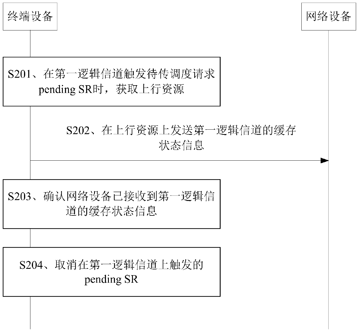
The embodiment of the invention provides a data transmission method and device, and the method comprises the steps: obtaining an uplink resource when a first logic channel triggers a to-be-transmittedscheduling request pending SR, the first logic channel being a logic channel which is not matched with any scheduling request configuration; cache state information of the first logic channel is senton the uplink resource; then, the pending SR triggered on the first logic channel is cancelled. In this way, the cache state information of the first logic channel can be sent through the physical uplink shared channel (PUSCH) resource indicated by the uplink authorization acquired in the non-random access mode, random access of the terminal device is avoided, and therefore the continuity of services on the logic channel is improved.

Description

technical field [0001] The present application relates to the field of communication technologies, and in particular, to a data transmission method and device. Background technique [0002] With the rapid development of wireless communication technology, the fifth generation (5th Generation, 5G) wireless communication technology has become a hot spot in the current industry. 5G wireless communication technology is an extension of the fourth generation (4th Generation, 4G) wireless communication technology. Therefore, the 5G communication system is called "Super 4G network", or "Post Long Term Evolution (Long Term Evolution, LTE) system", or New Radio (New Radio, NR). [0003] During data transmission, the network device can configure multiple logical channels (Logical Channel) for the terminal device. When there is data to be transmitted on a logical channel, and the terminal device does not have an available uplink shared channel (Physical Uplink Shared Channel). Channel,...

Claims


Application Information

Patent Timeline
Patent Type & Authority Applications(China)
IPC IPC(8): H04W28/02H04W72/12
CPCH04W28/0278H04W72/1268H04W28/02H04W72/12
Inventor 李小仙
Owner HUAWEI TECH CO LTD
Learn More