
Fan

A fan and air intake technology, which is applied in the direction of mechanical equipment, machine/engine, liquid fuel engine, etc., can solve the problems affecting the life of the motor, rotation deflection shaking, radial deformation of the output shaft, etc., to improve life, reduce rotation shaking, The effect of improving stability

Pending Publication Date: 2020-07-17
长沙洛丹青环保科技有限公司
View PDF0 Cites 0 Cited by
  • Summary
  • Abstract
  • Description
  • Claims
  • Application Information

AI Technical Summary

Problems solved by technology

[0003] Usually, the output shaft of the driving mechanism (motor) of the fan drives the impeller group of the fan to rotate, but usually the weight of the impeller group is transferred to the output shaft of the driving mechanism (motor), so that the output shaft of the driving mechanism (motor) not only needs to output The torque also bears the radial load. Long-term use will cause radial deformation of the output shaft, resulting in rotation deflection and shaking, which seriously affects the life of the motor.

Method used


Image

  • Fan
  • Fan
  • Fan

Examples


Embodiment Construction

[0024] The present invention will be described in detail below in conjunction with the accompanying drawings and embodiments.

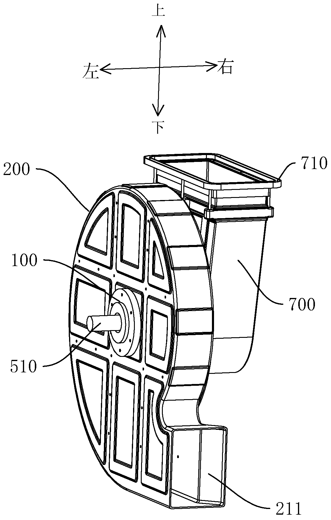
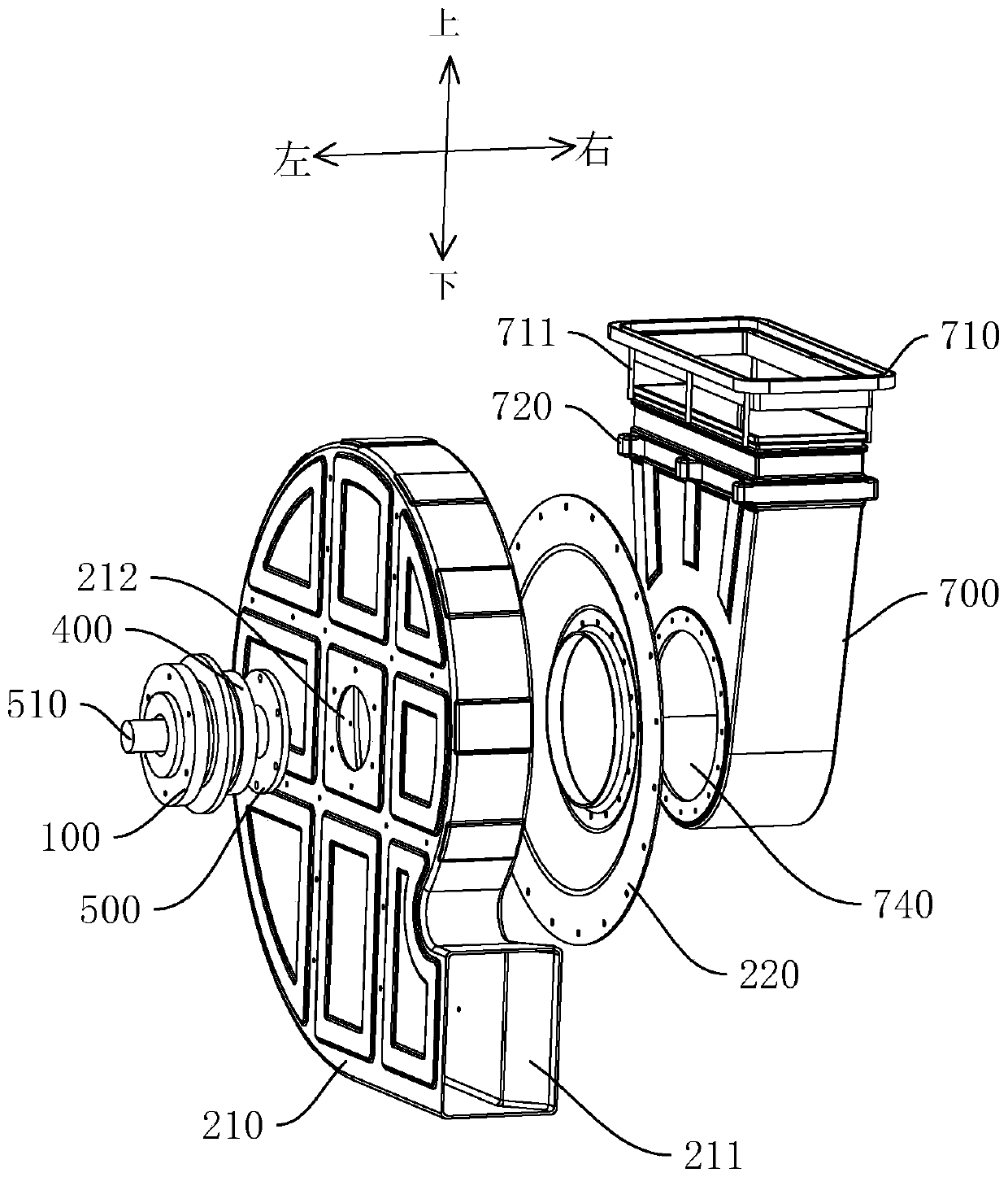
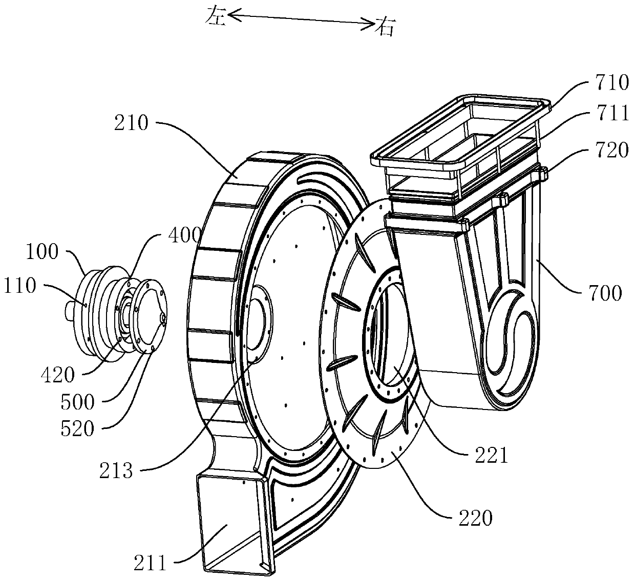
[0025] refer to Figure 1 to Figure 6 , a fan embodiment of the present invention includes a support frame 100 , a volute 200 , a connecting shaft 300 , an impeller set and a transmission member 500 .

[0026] The present invention can be applied to various fans, and the structure of the present invention will be described in detail below through an example of a centrifugal fan. The supporting frame 100 is used for installing fixed components and directly or indirectly contacting the ground to transfer the bearing gravity load to the ground. The supporting frame 100 is usually in contact with the ground through a base (not shown) at the bottom.

[0027] The volute 200 is in the shape of a flat cylinder as a whole, and the surface can be coated with a wear-resistant coating to improve wear resistance. The volute 200 is hollow inside and has an air in...


PUM


Abstract

The invention discloses a fan. The fan comprises a supporting frame, a volute, a connecting shaft, an impeller set and a transmission part, wherein the volute is connected to the supporting frame, theinterior of the volute is hollow, and the volute is provided with an air inlet and an air outlet; the connecting shaft is connected to the supporting frame, and at least part of the connecting shaftextends into the volute; the impeller set is used for driving air in the volute to be sent out from the air outlet during rotation and comprises an impeller base and blades connected to the outer periphery of the impeller base, and the part, extending into the volute, of the connecting shaft is rotationally sleeved with the impeller base; and the transmission part is used for being connected witha driving mechanism to obtain rotation power and connected with the impeller base to transmit torque. According to the impeller set, the driving mechanism connected with the transmission part does notneed to bear the gravity load of the impeller set, the service life of the driving mechanism is prolonged, the stability of the fan is improved, and rotation shaking caused by deformation is reduced.

Description

technical field [0001] The invention relates to the field of fans, in particular to a fan. Background technique [0002] Fans are widely used in ventilation, dust removal and cooling of factories, mines, tunnels, cooling towers, vehicles, ships and buildings; ventilation and induction of boilers and industrial furnaces; cooling and cooling of air conditioning equipment and household electrical appliances Ventilation; drying and selection of grain; wind tunnel wind source and inflation and propulsion of hovercraft, etc. [0003] Usually, the output shaft of the driving mechanism (motor) of the fan drives the impeller group of the fan to rotate, but usually the weight of the impeller group is transferred to the output shaft of the driving mechanism (motor), so that the output shaft of the driving mechanism (motor) not only needs to output The torque also bears radial loads. Long-term use will cause radial deformation of the output shaft, resulting in rotational deflection and...

Claims


Application Information

Patent Timeline
Patent Type & Authority Applications(China)
IPC IPC(8): F04D17/16F04D29/62F04D29/42F04D29/28F04D29/053F04D29/66
CPCF04D17/16F04D29/053F04D29/263F04D29/281F04D29/4213F04D29/4233F04D29/626F04D29/668
Inventor 段钢
Owner 长沙洛丹青环保科技有限公司
Learn More