Inclined pull anchor type floating tunnel structure extended by relay of artificial islands

A technology of floating tunnels and artificial islands, applied in the field of underwater floating tunnels, can solve problems such as difficult to predict comfort and safety risks, high cost, and difficult construction

Active Publication Date: 2020-07-17
CCCC THIRD HARBOR ENG +1
View PDF7 Cites 5 Cited by
  • Summary
  • Abstract
  • Description
  • Claims
  • Application Information

AI Technical Summary

Problems solved by technology

The buoy-type floating tunnel is suspended on the buoy on the water surface through anchor cables or anchor chains. The gravity of the tunnel is greater than the buoyancy, and the vertical direction is greatly affected by the fluctuation of the tide level; On the anchorage foundation below the bed, the gravity of the tunnel is less than the buoyancy, and the tunnel will displace or shake under the action of hydrodynamic forces; the pier-column type is actually a tunnel bridge supported on underwater pier columns, and the construction is difficult and expensive
Since the tunnel floats in the water, the installation and construction of the tunnel is affected by wind, waves, currents and ship waves. The underwater positioning of the three types of tunnels and the underwater or underwater docking construction are very difficult, and the comfort and safety of the underwater operation period Risks are unpredictable

Method used


Image

  • Inclined pull anchor type floating tunnel structure extended by relay of artificial islands
  • Inclined pull anchor type floating tunnel structure extended by relay of artificial islands
  • Inclined pull anchor type floating tunnel structure extended by relay of artificial islands

Examples


Embodiment Construction

[0083] The present invention will be further described below in conjunction with accompanying drawing.

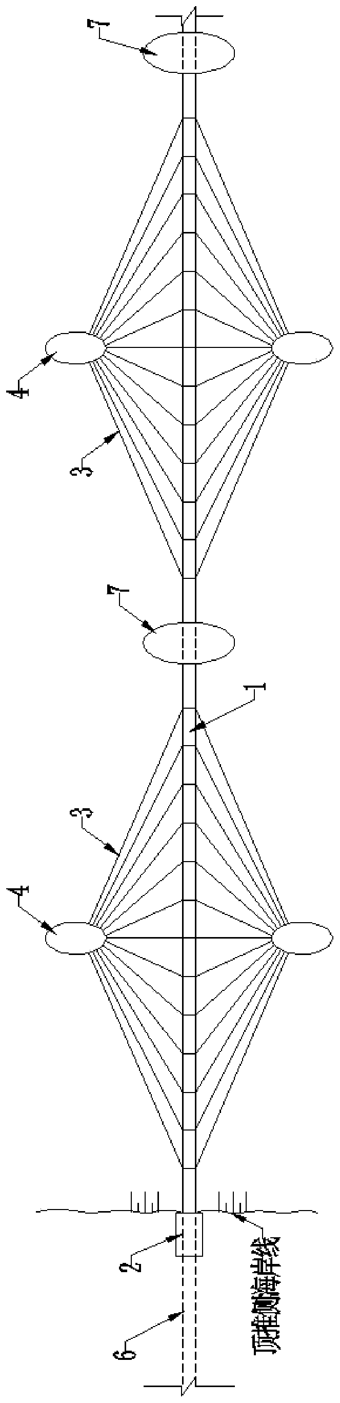
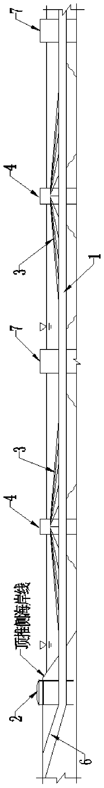
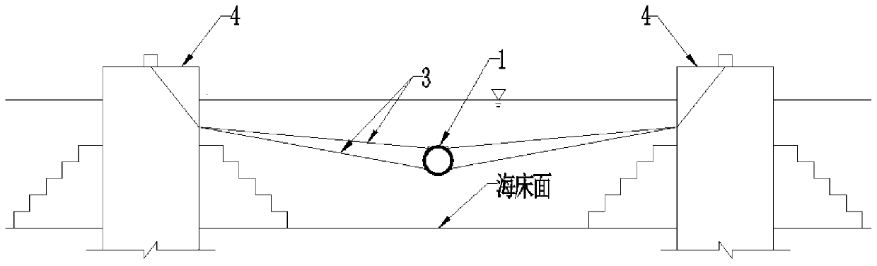
[0084] see Figure 1 to Figure 20 , the cable-stayed anchorage suspension tunnel structure of the artificial island relay extension of the present invention includes a tunnel body, a shore structure, several relay artificial islands 7 and a cable anchorage system, and also includes a buoyancy-to-weight ratio adjustment system and an anti-collision warning system , escape system and tunnel ancillary facilities. The shore structure includes a push-side shore structure 2 and a receiving-side shore structure that are arranged on the push-side coast and the receiving-side coast one by one; the tunnel body includes a floating tunnel 1 in water, a land slope tunnel 6 on the push-side and a receiving Side land slope tunnel; the water-facing end of the pushing-side land slope tunnel 6 and the water-facing end of the receiving-side land slope tunnel are in one-to-one correspondence ...


PUM


Abstract

The invention discloses an inclined pull anchor type floating tunnel structure extended by relay of artificial islands. The inclined pull anchor type floating tunnel structure comprises a pair of shore connecting structures, a submerged floating tunnel, the multiple relay artificial islands and a cable anchor system. The pair of shore connecting structures is connected with the two ends of a submerged floating tunnel and is connected between a pair of land-domain ramp tunnels. The submerged floating tunnel is formed by connecting multiple sections of pipe sections; and the relay artificial islands are arranged at intervals in the axis direction of the submerged floating tunnel, so that the whole submerged floating tunnel is divided into a plurality of span-floating tunnels. The cable anchor system comprises a plurality of pairs of cable anchor artificial islands and a plurality of sets of stay cables. The cable anchor artificial islands are arranged in the middle-span positions of twosides of each span-floating tunnel; and each set of stay cables is arranged between each span-floating tunnel and each pair of inhaul cable anchor artificial islands; and a set of island wall inhaul cable pipelines, inhaul cable protective sleeves, a set of inhaul cable steering piers, a cable ramp and a cable anchor pier are arranged on each cable anchor artificial island. The floating tunnel structure enables the length of the submerged floating tunnel to be greatly improved.

Description

technical field [0001] The invention relates to an underwater floating tunnel, in particular to a cable-stayed anchorage type floating tunnel structure with relay extension of an artificial island. Background technique [0002] The submerged floating tunnel, the English name is "Submerged Floating Tunnel", referred to as "SFT". In Italy, it is also called "Archimedes bridge", or "PDA" bridge for short. Generally, it consists of a tubular body floating at a certain depth in the water (the space of the tubular body is large enough to meet the requirements of road and railway traffic), a support system (anchor cables anchored on the seabed foundation, piers or floating boxes on the water) and It is composed of structures on both sides of the river. It is a new type of structure that means of transportation across the two banks separated by deep water. It is suitable for all means of transportation that need to pass through the water. It can pass trains, cars, small motor vehi...

Claims


Application Information

Patent Timeline
Patent Type & Authority Applications(China)
IPC IPC(8): E02D29/067E02D31/02E02D29/16
CPCE02D29/067E02D29/16E02D31/02
Inventor 徐立新蒋建荣孙洪春赵辉邱松杜宇谢锦波孙旭
Owner CCCC THIRD HARBOR ENG
Why Eureka
Try Eureka