An external supply system for artificial island pipe joints used in the relay extension of floating tunnels

A technology of suspended tunnels and artificial islands, applied in artificial islands, marine engineering, water conservancy projects, etc., can solve problems such as difficulty in predicting comfort and safety risks, displacement or shaking of tunnels, and difficulty in construction, saving construction time. , low cost, cost saving effect

Active Publication Date: 2021-07-13
CCCC THIRD HARBOR ENG
View PDF4 Cites 0 Cited by
  • Summary
  • Abstract
  • Description
  • Claims
  • Application Information

AI Technical Summary

Problems solved by technology

The buoy-type floating tunnel is suspended on the buoy on the water surface through anchor cables or anchor chains. The gravity of the tunnel is greater than the buoyancy, and the vertical direction is greatly affected by the fluctuation of the tide level; On the anchorage foundation below the bed, the gravity of the tunnel is less than the buoyancy, and the tunnel will displace or shake under the action of hydrodynamic forces; the pier-column type is actually a tunnel bridge supported on underwater pier columns, and the construction is difficult and expensive
Since the tunnel floats in the water, the installation and construction of the tunnel is affected by wind, waves, currents and ship waves. The underwater positioning of the three types of tunnels and the underwater or underwater docking construction are very difficult, and the comfort and safety of the underwater operation period Risks are unpredictable
[0005] The floating tunnel is located in deep water. If the tunnel is too long, it will be difficult to solve the problems of ventilation and escape.

Method used


Image

  • An external supply system for artificial island pipe joints used in the relay extension of floating tunnels
  • An external supply system for artificial island pipe joints used in the relay extension of floating tunnels
  • An external supply system for artificial island pipe joints used in the relay extension of floating tunnels

Examples


Embodiment Construction

[0046] The present invention will be further described below in conjunction with accompanying drawing.

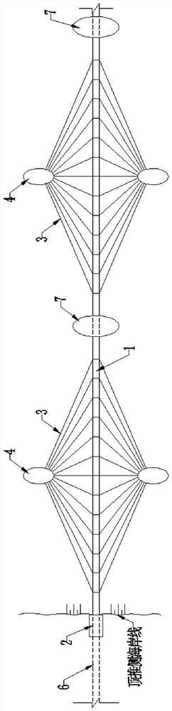
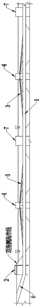
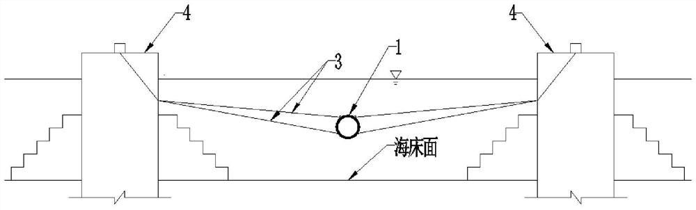
[0047] see first Figure 1 to Figure 3 , the artificial island pipe joint self-supply system for the relay extension of the floating tunnel according to the present invention, the applicable cable-stayed anchorage floating tunnel for the relay extension of the artificial island includes a tunnel body, a shore structure, several relay artificial islands 7 and cable anchorage system. The shore structure includes a push-side shore structure 2 and a receiving-side shore structure that are arranged on the push-side coast and the receiving-side coast one by one; the tunnel body includes a floating tunnel 1 in water, a land slope tunnel 6 on the push-side and a receiving Side land slope tunnel; the water-facing end of the pushing-side land slope tunnel 6 and the water-facing end of the receiving-side land slope tunnel are in one-to-one correspondence with the backwater end of the...


PUM


Abstract

The invention discloses an artificial island pipe joint external supply system for the relay extension of a floating tunnel, including a material wharf, a breakwater and a harbor basin arranged outside the island, and a pipe joint transfer dock, a transition channel and a pipe joint arranged inside the island. The pipe joint turns to the platform. The material wharf is located at the inner end of the outer part of the island and is located on the side of the shore structure on the pushing side of the artificial island; the breakwater is located at the countercurrent end of the relay artificial island; It is located on one side of the receiving side of the artificial island; the pipe joint transfer dock includes a dock, a dock room and a dock tail; the transition channel is set between the dock tail and the pipe joint connection system of the artificial island; the pipe joint steering platform is set on the artificial island Between the receiving side shore structure of the artificial island and the pushing side shore structure of the artificial island of the pipe joint connection system. The pipe joint external supply system of the artificial island of the present invention provides a convenient pipe joint supply mode for the installation of the pipe joints in the extension section of the floating tunnel, and the cost is low.

Description

technical field [0001] The invention relates to an underwater floating tunnel, in particular to an external supply system for artificial island pipe joints used for the relay extension of the floating tunnel. Background technique [0002] The submerged floating tunnel, the English name is "Submerged Floating Tunnel", referred to as "SFT". Also known as "Archimedes Bridge" in Italy. The difference between floating tunnels in water and traditional buried tunnels or excavated tunnels is that the floating tunnel structure is surrounded by water, neither on the ground nor through the ground, but mainly depends on the gravity of its own structure, the buoyancy and support of the structure The anchoring force of the system is used to keep it in a fixed position. The suspension tunnel is sealed all around, and this structure has all the characteristics of ordinary tunnels, and should be considered as a "tunnel" rather than a "bridge" from the point of view of use. [0003] Althou...

Claims


Application Information

Patent Timeline
Patent Type & Authority Patents(China)
IPC IPC(8): E02D29/067E02B3/06E02B3/10E02D27/40B63C1/12
CPCB63C1/12E02B3/068E02B3/10E02D27/40E02D29/067Y02A10/11
Inventor 徐立新尹海卿孙洪春莫亚思赵辉于文津周睿熠严昇
Owner CCCC THIRD HARBOR ENG
Why Eureka
Try Eureka