
Gravity type anti-overturning device suitable for single-pier bridge

A gravity-type, anti-overturning technology, applied in bridges, bridge parts, bridge construction, etc., can solve the problems of device and bridge damage, difficult construction, long construction period, etc., and achieve the effect of preventing overturning, convenient construction and low cost

Pending Publication Date: 2020-07-17
NANCHANG UNIV
View PDF0 Cites 12 Cited by
  • Summary
  • Abstract
  • Description
  • Claims
  • Application Information

AI Technical Summary

Problems solved by technology

For existing single-pillar bridges, it is not easy to adjust the support eccentricity of the middle pier. Generally, the bridge structure is strengthened by changing the bridge structure, so as to improve its anti-overturning stability. Adding a cover beam at the top, but this method has a long construction period and is difficult to construct; compared to changing the bridge structure, it is easier to add a connecting device for the upper and lower structures. This method uses the vertical bearing capacity of the connecting device itself to resist the live load. The vertical negative reaction force of the lower bridge support can avoid the phenomenon of the support being empty, and has the advantages of simple construction, saving space and materials, etc. The device itself causes an excessive bending moment, and at the same time, it will also generate a large additional force on the bridge, thus causing damage to the device and the bridge itself

Method used


Image

  • Gravity type anti-overturning device suitable for single-pier bridge
  • Gravity type anti-overturning device suitable for single-pier bridge
  • Gravity type anti-overturning device suitable for single-pier bridge

Examples


Embodiment Construction

[0026] Below the present invention is further described:

[0027] see Figure 1-5 ,

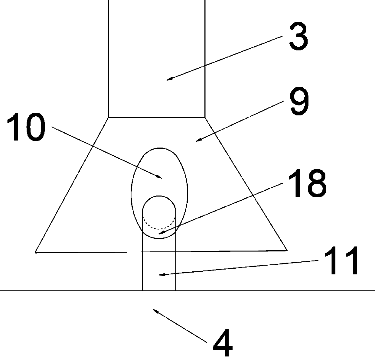
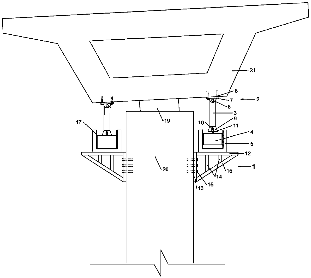
[0028] The invention discloses a gravity type anti-overturning device suitable for a single column pier bridge, which comprises a steel corbel 1, a fixed hinge support 2, a tie rod 3, a lead post 4 and a square stopper 5; the steel corbel 1 is fixed On the side of the pier 20, the square block 5 is a hollow square structure with an open top, and its bottom is fixed on the top of the steel corbel 1; the lead column 4 is placed inside the cavity of the square block 5 One end of the pull rod 3 is connected to the top of the lead column 4, and the other end is hinged to the fixed hinge support 2; the fixed hinge support 2 is fixed on both sides of the bottom of the beam body 21.

[0029] Described steel corbel 1 comprises steel corbel top plate 12, steel corbel inner plate 13, steel corbel bottom plate 15 and steel corbel web 14, and described steel corbel inner plate 13 is provided with severa...


PUM


Abstract

The invention discloses a gravity type anti-overturning device suitable for a single-pier bridge. The gravity type anti-overturning device comprises a steel corbel, fixed hinge supports, a pull rod, alead column and a square stop block. The steel corbel is fixed to the side face of a pier, the square stop block is of a hollow square structure with an opening in the top, and the bottom of the square stop block is fixed to the top of the steel corbel. The lead column is placed in the cavity of the square stop block; one end of the pull rod is connected with the top of the lead column, and the other end is hinged with the fixed hinge support; and the fixed hinge supports are fixed to the two sides of the bottom of the beam body. The anti-overturning device has good anti-overturning performance, eccentric loads borne by the bridge support are balanced by means of the gravity of the lead column and the supporting force of the lead column on the other side to the pull rod, the support is prevented from disengaging, the anti-overturning device can well adapt to rotation of a beam body, and extra bending moment damage to a bridge and a device is avoided; in addition, the structure is simple, construction is convenient and fast, and cost is low.

Description

technical field [0001] The invention belongs to the technical field of bridge engineering, and in particular relates to a gravity anti-overturning device suitable for single-pillar pier bridges. Background technique [0002] At present, in order to improve the anti-overturning ability of bridges with single-pillar piers and enhance their lateral stability, the main measures taken are: changing the bridge structure, adjusting the support eccentricity of the middle pier, and adding connecting devices for the upper and lower structures. For existing single-pillar bridges, it is not easy to adjust the support eccentricity of the middle pier. Generally, the bridge structure is strengthened by changing the bridge structure, so as to improve its anti-overturning stability. Adding a cover beam at the top, but this method has a long construction period and is difficult to construct; compared to changing the bridge structure, it is easier to add a connecting device for the upper and l...

Claims


Application Information

Patent Timeline
Patent Type & Authority Applications(China)
IPC IPC(8): E01D19/04E01D19/00
CPCE01D19/00E01D19/042
Inventor 田钦宋鹏糜宇黎学桐
Owner NANCHANG UNIV
Learn More