
Cutting and welding device used for replacement of cutting edge blade of grab bucket of ship unloader and application method of cutting and welding device

A cutting edge plate and ship unloader technology, applied in the direction of auxiliary devices, electrode support devices, welding rod characteristics, etc., can solve the problems of many welders invested, slow welding speed, edge plate thickness, etc., to meet production needs and low cost , the effect of short construction period

Inactive Publication Date: 2020-07-17
MCC BAOSTEEL TECH SERVICE
View PDF8 Cites 2 Cited by
  • Summary
  • Abstract
  • Description
  • Claims
  • Application Information

AI Technical Summary

Problems solved by technology

The on-site construction of this project has the following problems: 1) Many welders are invested in the maintenance of the grab bucket; 2) After the excavation and splicing are completed, the welding volume is large; 3) The cutting edge plate is thick (60mm), and the welding speed is slow

Method used


Image

  • Cutting and welding device used for replacement of cutting edge blade of grab bucket of ship unloader and application method of cutting and welding device
  • Cutting and welding device used for replacement of cutting edge blade of grab bucket of ship unloader and application method of cutting and welding device
  • Cutting and welding device used for replacement of cutting edge blade of grab bucket of ship unloader and application method of cutting and welding device

Examples


Embodiment Construction

[0049] The specific implementation manners of the present invention will be described in further detail below in conjunction with the accompanying drawings. These embodiments are only used to illustrate the present invention, not to limit the present invention.

[0050] In the description of the present invention, it should be noted that the orientations or positional relationships indicated by the terms "upper", "lower", "top", "bottom", "inner" and "outer" are based on the orientations shown in the drawings Or positional relationship is only for the convenience of describing the present invention and simplifying the description, but does not indicate or imply that the device or element referred to must have a specific orientation, be constructed and operated in a specific orientation, and therefore should not be construed as limiting the present invention.

[0051] In the description of the present invention, it should be noted that unless otherwise specified and limited, th...


PUM


Abstract

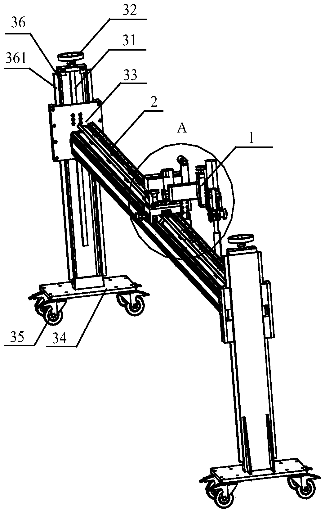
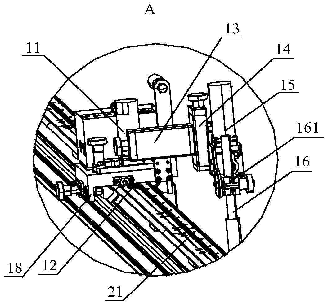
The invention provides a cutting and welding device used for replacement of a cutting edge blade of a grab bucket of a ship unloader. The cutting and welding device comprises a rail, manual lifting portals and movable cutting and welding equipment. The manual lifting portals comprise portal bodies, lead screws and nuts, the lead screws extend in the Z-axis direction and penetrate through the topsof the portal bodies, handles are arranged at the top ends of the lead screws, and the ends of the rail are connected with the nuts through mounting portions. The movable cutting and welding equipmentcomprises a rack arranged on the rail, a Y-axis walking motor mounted on the rack and cutting and welding equipment, the Y-axis walking motor drives the rack to move along the rail, an X-axis walkingmotor, a Z-axis walking motor and a rotating motor which are connected sequentially are further arranged on the rack, and an output shaft of the rotating motor is connected with the cutting and welding equipment. The cutting and welding device has the beneficial effects that heat source moving in the cutting and welding processes of the cutting edge plate is completed by a mechanical device, cutting and welding angles are adjusted through cooperation of operation personnel, and linear parts can be cut and welded rapidly and stably. The whole work process is simple and convenient, the construction period is short, and the cost is low.

Description

technical field [0001] The invention relates to the technical field of mechanical equipment maintenance, in particular to a cutting and welding device for replacing a grab edge plate of a ship unloader and a method for using the same. Background technique [0002] The large-scale bridge grab ship unloader is a large-scale hoisting machinery widely used in wharves, responsible for lifting operations on water, and its grab is an important part of the ship unloader. Due to the harsh environment of the raw material wharf and the long-term wear of the grab, the maintenance cycle of the grab is relatively short, and it needs to be disassembled and repaired after the usage time expires. When repairing the grab bucket, it is necessary to disassemble the grab bucket as a whole, and replace the 6 cutting edge plates (plate thickness 50mm) of the grab bucket. The on-site construction of the project has the following problems: 1) Many welders are invested in the maintenance of the grab...

Claims


Application Information

Patent Timeline
Patent Type & Authority Applications(China)
IPC IPC(8): B23K9/013B23K9/12B23K9/16B23K9/28B23K7/00B23K7/10B23K37/02
CPCB23K7/00B23K7/102B23K9/013B23K9/12B23K9/16B23K9/28B23K37/0211
Inventor 张君杨荣青董辉金晓荣侯郜俊柯陆伟吴君
Owner MCC BAOSTEEL TECH SERVICE
Learn More