
A loop-based iq imbalance adaptive blind compensation method and system

A compensation method and compensation system technology, applied in the field of communication, can solve the problems of difficult system adjustment algorithm structure, high cost, high compensation performance, etc., and achieve the effects of reducing compensation cost, improving performance, and strong robustness

Active Publication Date: 2021-10-26
SOUTH CHINA UNIV OF TECH
View PDF5 Cites 0 Cited by
  • Summary
  • Abstract
  • Description
  • Claims
  • Application Information

AI Technical Summary

Problems solved by technology

[0003] A common way to suppress IQ imbalance is to start from the hardware and use high-performance analog devices (filters, amplifiers, analog-to-digital converters, etc.), although high-performance analog devices can fundamentally suppress the impact of IQ imbalance , but high-performance analog devices are generally larger in size and higher in cost, which correspondingly increases the power consumption and price of mobile transceiver equipment
In addition, high-performance analog devices cannot completely suppress IQ imbalance, and the ability to suppress IQ imbalance in different environments (temperature, humidity, etc.) will be different, so suppressing IQ imbalance in the analog domain is not very practical
If you cannot start from the analog domain, you can only suppress and compensate the IQ imbalance in the digital domain through digital signal processing.
[0004] However, the existing IQ imbalance compensation algorithms in the digital domain are often difficult to balance high compensation performance and low computational complexity, and it is also difficult to adjust the algorithm structure for different systems

Method used


Image

  • A loop-based iq imbalance adaptive blind compensation method and system
  • A loop-based iq imbalance adaptive blind compensation method and system
  • A loop-based iq imbalance adaptive blind compensation method and system

Examples


Embodiment 1

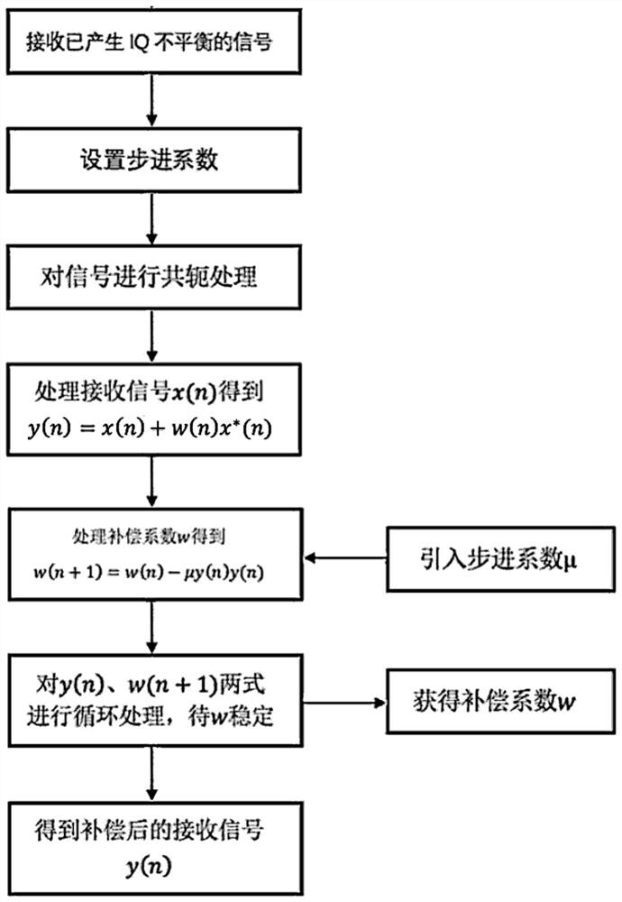
[0090] A loop-based adaptive blind compensation method for IQ imbalance, such as figure 1 As shown, it mainly includes:

[0091] Receive the IQ unbalanced signal, set the step coefficient, process the received signal, introduce the step coefficient to obtain the compensation coefficient through cyclic iteration, and then obtain the compensated output signal. The detailed implementation process will be analyzed below.

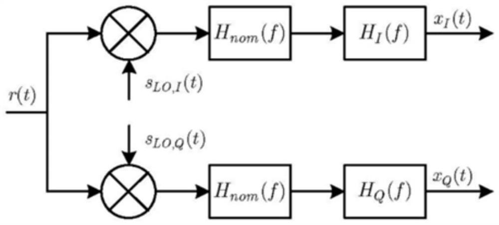
[0092] figure 2 It is a schematic diagram of signal IQ imbalance, which shows the IQ imbalance generated by the signal due to the influence of non-ideal factors in the process of receiving the signal, where: H nom (f) represents the frequency response of the low-pass filter on the link, H I (f) and H Q (f) respectively represent the frequency responses of the I-way and Q-way carrier signals after they pass through the link and are affected by other non-ideal factors (ideally, H I (f)=H Q (f)=1), g and represent the mismatch magnitude and mismatch phase, ...

Embodiment 2

[0154] A loop-based IQ imbalance adaptive blind compensation system, comprising:

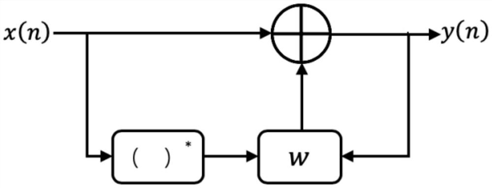
[0155] Receiving module: used to receive the unbalanced signal x(n) through the two channels of I and Q, and intercept the discrete signal of a certain length.

[0156] Fixed-point processing module: for performing fixed-point processing on the received signal x(n).

[0157] Setting module: used to set the step factor. In the process of setting the step coefficient of the setting module: set the initial step coefficient to be relatively large, perform rough calibration, and after processing a certain amount of data, set a smaller step coefficient to perform fine calibration.

[0158] Conjugate module: used to conjugate the received signal x(n) to obtain x * (n).

[0159] Compensation module: used to process the received signal x(n) to obtain the compensated output signal y(n)=x(n)+w(n)x * (n), where w(n) is the compensation coefficient;

[0160] Loop module: used to introduce the step coeff...


PUM


Abstract

The invention belongs to the technical field of communications, and relates to a loop-based IQ imbalance self-adaptive blind compensation method, comprising: receiving an unbalanced signal x(n) through two channels of I and Q, and intercepting a discrete signal of a certain length; Set the step factor; perform conjugate processing on the received signal x(n) to get x * (n); process the received signal x(n) to obtain the compensated output signal y(n)=x(n)+w(n)x * (n), where w(n) is the compensation coefficient; the step coefficient is introduced and the compensation coefficient w(n) is smoothed, and the compensation coefficient w(n) required by the system is obtained by loop iteration, and then the compensated The output signal y(n) of . The IQ imbalance adaptive blind compensation method of the present invention is able to operate in any quadrature receiver setup, whether single or multi-channel, and is independent of any specific structure or characteristics of the ideal baseband equivalent signal. The invention also provides a loop-based IQ imbalance adaptive blind compensation system.

Description

technical field [0001] The invention belongs to the technical field of communication, and relates to a cycle-based IQ imbalance self-adaptive blind compensation method and system. Background technique [0002] IQ imbalance refers to the amplitude and phase mismatch between in-phase (In-phase, I) and quadrature-phase (Quadrature-phase, Q) branches of a transmitter and a receiver. Ideally, the in-phase and quadrature branches have equal magnitude gain and 90-degree phase deviation. However, in an actual communication system, it is usually difficult to realize the above ideal situation, thus resulting in IQ imbalance. In the transmitter, non-ideal up-conversion, unbalanced filters and digital-to-analog converters in the I and Q branches, etc. may generate IQ imbalance. At the receiver, non-ideal down-conversion, unbalanced filters in the I and Q branches, amplification, and sampling can all cause IQ imbalance. [0003] A common way to suppress IQ imbalance is to start from t...

Claims


Application Information

Patent Timeline
Patent Type & Authority Patents(China)
IPC IPC(8): H04L27/00H04L27/38
CPCH04L27/0014H04L27/389H04L2027/0024
Inventor 吕方明贺小勇
Owner SOUTH CHINA UNIV OF TECH
Learn More