
Digital beam forming method based on zero intermediate frequency architecture

A digital beam and zero-IF technology, applied in the field of digital beamforming based on zero-IF architecture, can solve the problems of low integration, poor multi-beam flexibility, and large system volume, and achieve the effect of reducing system volume and power consumption

Inactive Publication Date: 2020-07-14
XIDIAN UNIV
View PDF8 Cites 9 Cited by
  • Summary
  • Abstract
  • Description
  • Claims
  • Application Information

AI Technical Summary

Problems solved by technology

[0004] 1. Most of the phase shifters and attenuators in the RF front-end have an accuracy of 5 to 7 digits. Although they can meet the requirements of some civil and military fields, their accuracy is still low in higher-performance anti-jamming radar and communication equipment. not enough
[0005] 2. The integration level is low. The system receiver and transmitter are generally superheterodyne structures, which require a large number of inductance and capacitor devices to filter out intermediate frequency clutter signals, which are difficult to integrate inside the chip, resulting in a large system size
[0006] 3. The flexibility of multi-beam forming is poor. In the multiple-receive and multiple-transmit MIMO radar and multiple-receive and multiple-transmit MIMO communication systems, the number of main lobes of the beam is limited by the number of channels of the system’s analog-to-digital converter and digital-to-analog converter. Each transmit channel and receive channel corresponds to a specific number of antenna units, and the antenna units cannot be reused between channels, making it difficult to adapt to complex and changeable space environments

Method used


Image

  • Digital beam forming method based on zero intermediate frequency architecture
  • Digital beam forming method based on zero intermediate frequency architecture
  • Digital beam forming method based on zero intermediate frequency architecture

Examples


Embodiment Construction

[0023] The present invention is described in detail below in conjunction with accompanying drawing and embodiment:

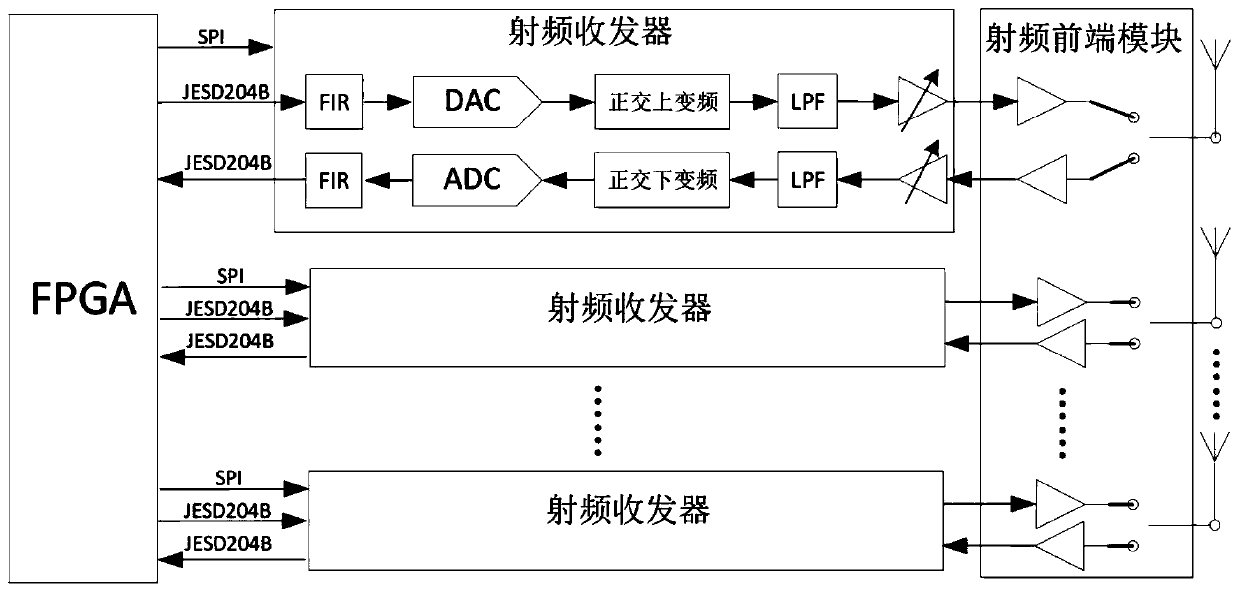
[0024] refer to figure 1 , the zero-IF architecture system used in the present invention is mainly composed of three parts, wherein the first part is an FPGA, the second part is a radio frequency transceiver, and the third part is a radio frequency front-end module.

[0025] Described FPGA is used for the control of digital signal processing and interface circuit, carries out software configuration to radio frequency transceiver through SPI interface, carries out the receiving and sending of baseband digital signal to radio frequency transceiver through JESD204B high-speed serial data link;

[0026] Described radio frequency transceiver, its model selection can be the models such as AD9371, ADRV9009 and ADRV9026 of Analog Devices Semiconductor ADI Company, is used for carrying out baseband digital signal FIR filtering, digital-to-analog conversion, analog-to-dig...


PUM


Abstract

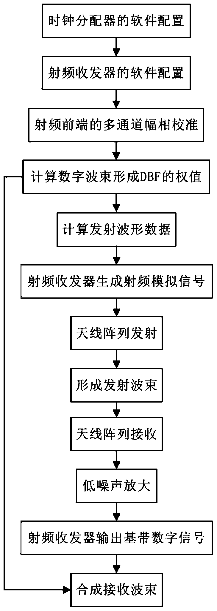
The invention discloses a digital beam forming method based on a zero intermediate frequency architecture, and mainly solves the problems of low beam forming precision and poor flexibility in the prior art. The zero intermediate frequency architecture comprises an FPGA, a radio frequency transceiver and a radio frequency front-end module. According to an implementation solution, the method comprises the steps that an operation environment is initialized; the FPGA calculates the weight of the digital beam forming DBF, then calculates transmitted waveform data, and sends the transmitted waveformdata to the radio frequency transceiver to generate a radio frequency analog signal; the radio frequency analog signal is amplified and then transmitted through an antenna array to form a transmitting wave beam; the antenna array receives electromagnetic waves in the space, and after low-noise amplification, the electromagnetic waves are output by the corresponding radio frequency transceivers tobe baseband digital signals to be sent to the FPGA. And the FPGA synthesizes the baseband digital signals into a receiving wave beam. According to the method disclosed in the invention, the resolution, the real-time performance and the flexibility of beam forming are improved; each antenna unit can be flexibly separated and combined into a new sub-array, and the method can be applied to communication or radar to realize digital beam forming.

Description

technical field [0001] The invention belongs to the technical field of electronic information, in particular to a digital beam forming method based on a zero-IF architecture. It can be used for communication or radar systems on airborne, missile and satellite platforms. Background technique [0002] Phased array technology controls the direction and shape of the beam in space by changing the phase and amplitude of the signals sent and received by each antenna unit of the antenna array, that is, beamforming. Compared with the traditional mechanical scanning antenna, the phased array antenna has the advantages of fast scanning speed, multi-target tracking ability, high resolution, and strong anti-interference ability. [0003] At present, the commonly used phased array technology is an active phased array based on analog circuits. Each up-converted signal is divided into multiple signals by a power divider, and then the phase and amplitude are changed by a phase shifter and a...

Claims


Application Information

Patent Timeline
Patent Type & Authority Applications(China)
IPC IPC(8): H04B7/06
CPCH04B7/0617
Inventor 全英汇吴彬彬肖国尧李亚超邢孟道冯伟别博文柯华锋王旭
Owner XIDIAN UNIV
Learn More