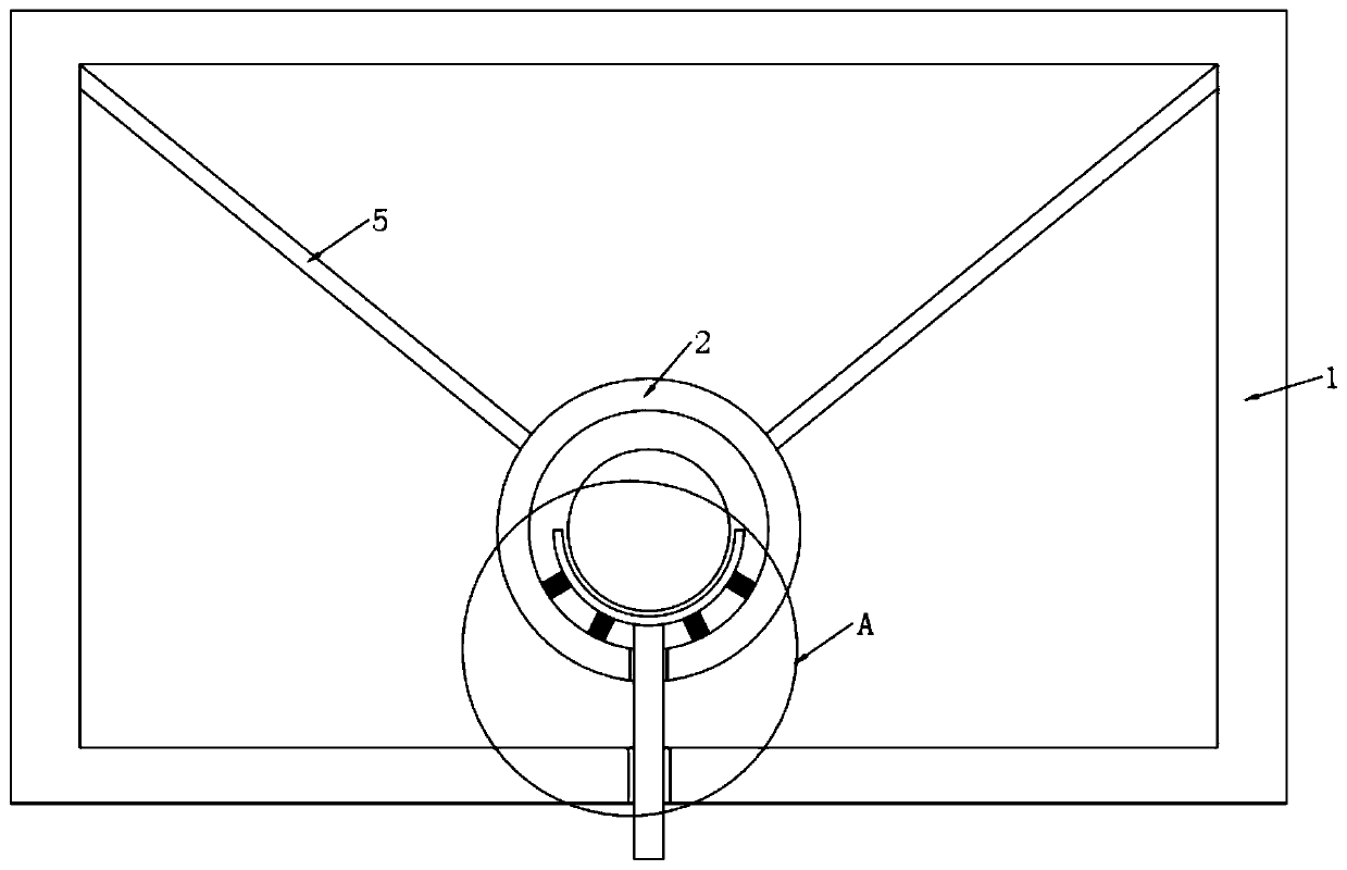
Building cable erection buffer protection bracket

A cable and construction technology, which is applied in the field of buffering and protecting brackets for building cables, can solve problems such as cable and buffering and anti-seismic brackets being damaged, affected, unable to protect cables and brackets, etc., and achieve good results

Active Publication Date: 2020-07-14
江峰
View PDF11 Cites 0 Cited by
  • Summary
  • Abstract
  • Description
  • Claims
  • Application Information

AI Technical Summary

Problems solved by technology

[0004] However, the above-mentioned elastic cushioning anti-seismic support and hanger structure still has the following obvious defects during use: if the support structure is subjected to continuous external force impact, for example, when a rod is placed obliquely or vertically on the cable, Although the above-mentioned support can realize the buffering and anti-vibration of the cable, after absorbing the buffer, the rod will still rest on the cable, and the long-term contact and pressure will cause damage and influence on the cable and the buffering and anti-seismic support, and it cannot be installed on the rod. As soon as the components cause vibration to the cable and need to be buffered, remove the external rods or components that are continuously placed on the cable to reduce the impact on the cables and brackets. Usually, subsequent manual operations on the rods or components are required. or mechanical removal, resulting in the inability to further protect cables and brackets when absorbing cushioning for shock resistance

Method used


Image

  • Building cable erection buffer protection bracket
  • Building cable erection buffer protection bracket
  • Building cable erection buffer protection bracket

Examples


Embodiment 1

[0037] Embodiment 1: as the description attached Figure 11 And attached Figure 12 As shown, when the inclined rod 200 is placed on the cable 100 from the left side, an external force will be provided to the cable 100 to generate vibration, and the cable 100 will be squeezed downward to the right. At this time, when the protective block 20 rotates to In the horizontal state, the cable 100 will slide along the inclined protection plate 22 and finally fall into the cable protection groove 21 , and the cable 100 will not be damaged by external force if the diagonal rod 200 is pushed away by the protection block 20 .

Embodiment 2

[0038] Embodiment two: as the description attached Figure 13 And attached Figure 14 As shown, when the vertical pole 300 falls from above and is placed on the cable 100, an external force will be provided to the cable 100 to generate up and down vibrations, and the cable 100 will be pressed downwards. At this time, the protective block 20 is activated to rotate to In the horizontal state, the cable 100 will directly fall into the cable protection slot 21 , and the vertical pole 300 will be pushed up by the protection block 20 and the cable 100 will no longer be damaged by external force.


PUM


Abstract

The invention discloses a building cable erection buffer protection bracket. The bracket comprises a bracket pipe and a bracket rod; the bracket pipe is fixedly connected with the bracket rod; a buffer pipe is fixedly arranged in the bracket pipe; buffer springs are connected to the inner side walls of a containing bottom plate and the buffer pipe; a lower insertion hole and a through hole are correspondingly formed in the buffer pipe and the bracket pipe in a vertical direction; a starting rod is movably inserted into the lower insertion hole and the through hole; one end of the starting rodis fixedly connected to the containing bottom plate; a protection block is fixedly connected to a rotating plate; a cable protection groove is formed in the protection block; and inclined protection plates are arranged on the two sides of the cable protection groove. According to the bracket of the invention, the buffer pipe is used in cooperation with the protection block used for synchronously protecting a cable at the same time through the starting rod while realizing buffering and shock resistance for the cable, manual operation is not needed any more, timeliness is good, and the cable andthe bracket can be protected when shock resistance is realized through buffering absorption.

Description

technical field [0001] The invention relates to the technical field of building buffer brackets, in particular to a buffer protection bracket for building cables. Background technique [0002] In people's daily life, or on construction and industrial production equipment, various mechanical vibrations are inevitable. In the process of anti-seismic support of various devices, equipment or building structures, only reinforcement is not the best way , to effectively buffer and absorb the vibration on the corresponding anti-seismic support and hanger is also an important measure to improve the anti-seismic and impact resistance of the anti-seismic support and hanger. How to buffer the vibration generated on the cable / connector and the corresponding support and hanger , absorption, and improving the anti-seismic and impact-resistant performance of anti-seismic supports and hangers has become a problem that needs to be solved. [0003] In the prior art, the notification number is...

Claims


Application Information

Patent Timeline
Patent Type & Authority Applications(China)
IPC IPC(8): H02G7/05H02G7/14F16F15/067
CPCF16F15/067H02G7/05H02G7/14
Inventor 沈贵宁沈恒宇
Owner 江峰
Why Eureka
Try Eureka