
Prefabricated floor secondary beam combined member

A combination component and assembly technology, applied in the direction of floors, building components, building structures, etc., can solve problems such as design difficulties, unclear combination functions, and overall plate falling, so as to increase anti-corrosion and fire resistance and save tension. The effect of solid connection, easy design and manufacture

Inactive Publication Date: 2020-07-14
BEIJING UNIV OF TECH
View PDF8 Cites 3 Cited by
  • Summary
  • Abstract
  • Description
  • Claims
  • Application Information

AI Technical Summary

Problems solved by technology

[0004] Some steel structure buildings will also use fully prefabricated traditional non-superimposed floor slabs. Although it is not necessary to cast concrete on site, after the prefabricated slabs are placed on the steel beams, the beams will also deflect under the weight of the floor slabs before they form a combined effect. Causes increased beam and floor deflection
When ordinary prefabricated floor slabs and steel beams are connected by pouring on site, due to the short tendons reserved, the connection strength between the slabs and between the slabs and the steel beams is not high. Combination action, unable to transmit bending moment
When an earthquake occurs, it is easy to separate from the beam, and the plate will fall as a whole, causing casualties and property losses.
If you want to fix the slab edges and withstand the bending moment, you need to reserve a long beard steel bar to meet the anchoring requirements, so that the connection area is very wide, and you need to support the formwork at the gap between the beams and slabs and then pour concrete , the construction steps are cumbersome
[0005] In the traditional steel frame structure, for design safety, when the two ends of the main girder bear the negative bending moment, the combined effect of the steel beam and the concrete floor is not considered. It is clear that it brings difficulties to the design, and the actual structure cannot guarantee strong columns and weak beams in earthquakes; moreover, the beams in the beam-column assembly system mostly use solid-web I-beams, which have a large dead weight and inconvenient pipeline layout, which affects indoor cleanliness. high

Method used


Image

  • Prefabricated floor secondary beam combined member
  • Prefabricated floor secondary beam combined member
  • Prefabricated floor secondary beam combined member

Examples


Embodiment Construction

[0045] In order to make the purpose, technical solutions and advantages of the embodiments of the present invention clearer, the technical solutions in the embodiments of the present invention will be clearly and completely described below in conjunction with the drawings in the embodiments of the present invention. Obviously, the described embodiments It is a part of embodiments of the present invention, but not all embodiments. Based on the embodiments of the present invention, all other embodiments obtained by persons of ordinary skill in the art without making creative efforts belong to the protection scope of the present invention.

[0046] In the description of the present invention, it should be noted that the terms "center", "upper", "lower", "left", "right", "vertical", "horizontal", "inner", "outer" etc. The indicated orientation or positional relationship is based on the orientation or positional relationship shown in the drawings, and is only for the convenience of...


PUM


Abstract

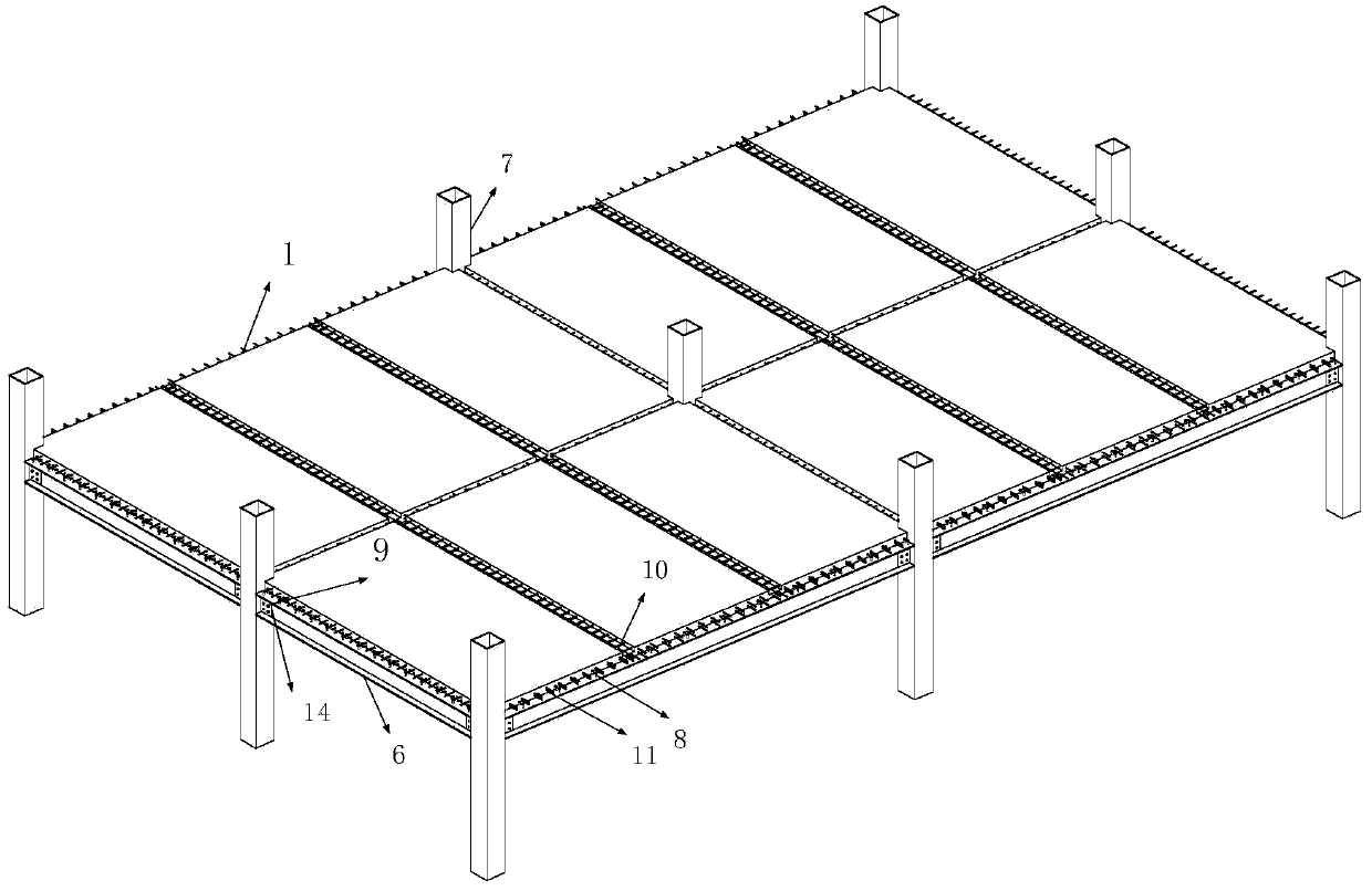
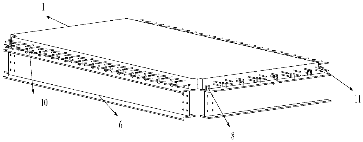
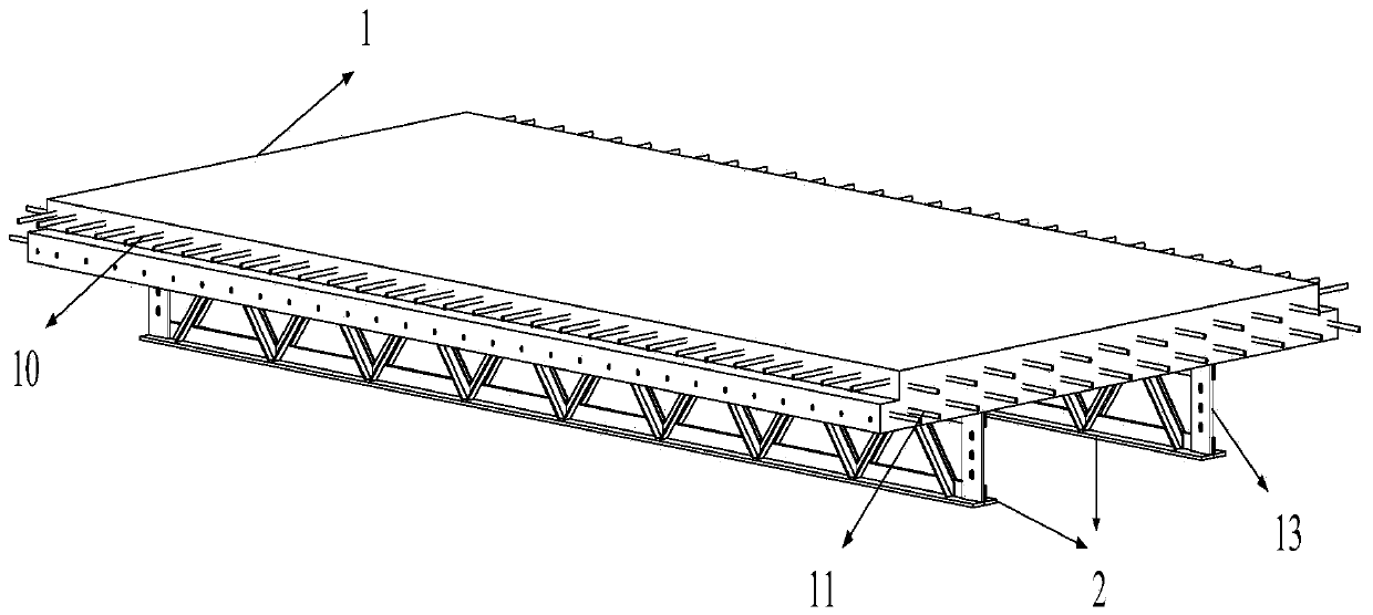
The invention discloses a prefabricated floor secondary beam combined member. The prefabricated floor secondary beam combined member comprises prefabricated floors, truss secondary beams and girders;the multiple prefabricated floors are built on a main frame spliced by the girders, grooves are formed in connection joints of the two adjacent prefabricated floors or connection joints of the two adjacent prefabricated floors and the girders, and pre-embedded pieces in the prefabricated floors and first fixing connection pieces on the girders extend out of the interiors of the grooves; concrete is poured in the grooves, and the prefabricated floors and the girders are connected; the upper parts of the truss secondary beams are fixed to the lower parts of the prefabricated floors, and fixing connection pieces connected with the prefabricated floors are arranged on the upper parts of the truss secondary beams; and connecting plates are arranged at two ends of the truss secondary beams, andthe truss secondary beams are connected with the girders through the connecting plates. According to the prefabricated floor secondary beam combined member, the prefabricated floors and the secondarybeams are combined together in a factory, the problem of initial immunity of the floors and the beams due to wet concrete is solved, and the purpose of increasing the strength and stiffness of the floors is achieved; and meanwhile, through the standardization and modularization of the prefabricated member, the workload is greatly reduced, and the construction speed is improved.

Description

technical field [0001] The invention belongs to the technical field of assembled prefabricated floor slab structures, and in particular relates to a composite prefabricated component for assembled concrete floor slab secondary beams. Background technique [0002] At present, in steel structure buildings, steel beams are generally installed first, and then corrugated steel plates are laid on the steel frame, and concrete is cast in place. Before the cast-in-place concrete is hardened, the beam and slab have not yet formed a combined action, and under the influence of the floor's own weight, the deflection of the steel beam in the construction stage increases. When designing steel beams, the steel strength cannot be fully utilized in order to meet the specification limits of deflection. [0003] For the currently popular concrete laminated floor slab, the factory prefabricates the first floor, and some steel bars need to be tied on site, and then a layer of concrete is poured...

Claims


Application Information

Patent Timeline
Patent Type & Authority Applications(China)
IPC IPC(8): E04B5/02E04B5/14
CPCE04B5/02E04B5/14
Inventor 刘学春陈美玲邓玉萍邓刚
Owner BEIJING UNIV OF TECH
Learn More