
An automatic jet-type dewatering cleaning device

A cleaning device and jet technology, which are applied in the directions of cleaning methods, cleaning methods and utensils, chemical instruments and methods using gas flow, etc. Good effect and strong function expansion effect

Active Publication Date: 2021-05-11
浙江先导热电科技股份有限公司
View PDF1 Cites 0 Cited by
  • Summary
  • Abstract
  • Description
  • Claims
  • Application Information

AI Technical Summary

Problems solved by technology

[0004] In order to overcome the problems in the prior art that the cleaning process and cleaning method of thermoelectric products after the welding process are done manually, the production efficiency is low, and the labor intensity of workers is high, the present invention provides an automatic air jet type water removal cleaning device, which has the function of water removal High cleaning efficiency, wide application range, good feasibility, easy operation, strong function expansion, etc.

Method used


Image

  • An automatic jet-type dewatering cleaning device
  • An automatic jet-type dewatering cleaning device
  • An automatic jet-type dewatering cleaning device

Examples


Embodiment 1

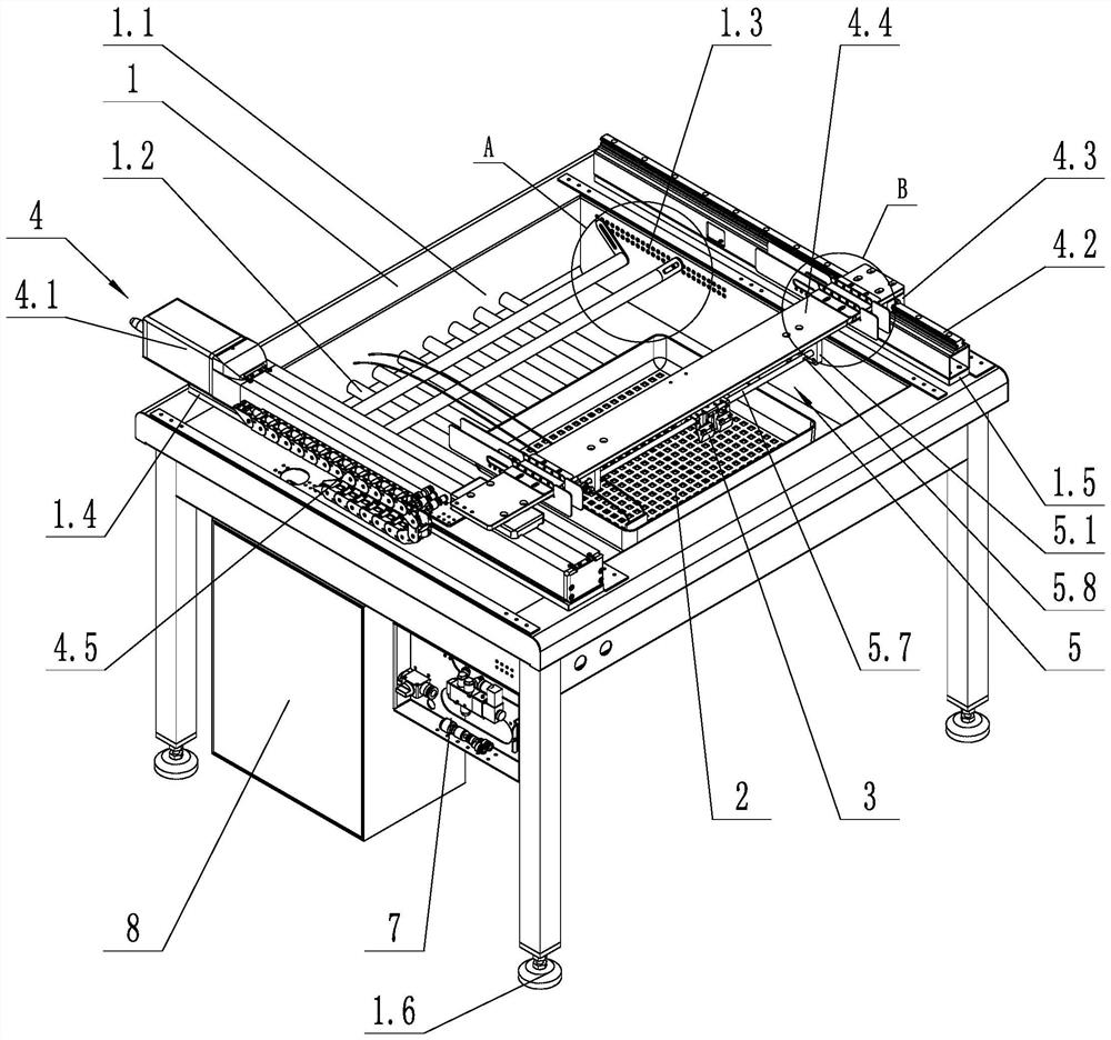
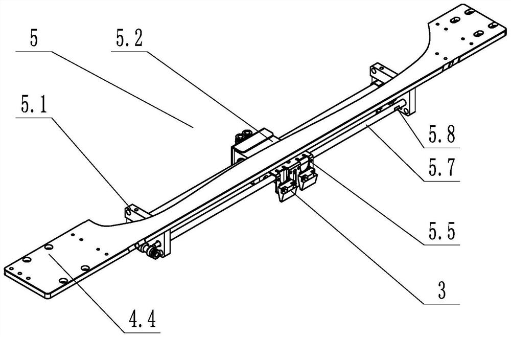
[0033] Such as figure 1 As shown, an automatic jet-type water removal and cleaning device includes a sink table 1, a cleaning basket 2, an air jet structure 3, an X-axis driving structure 4 and a Y-axis driving structure 5.

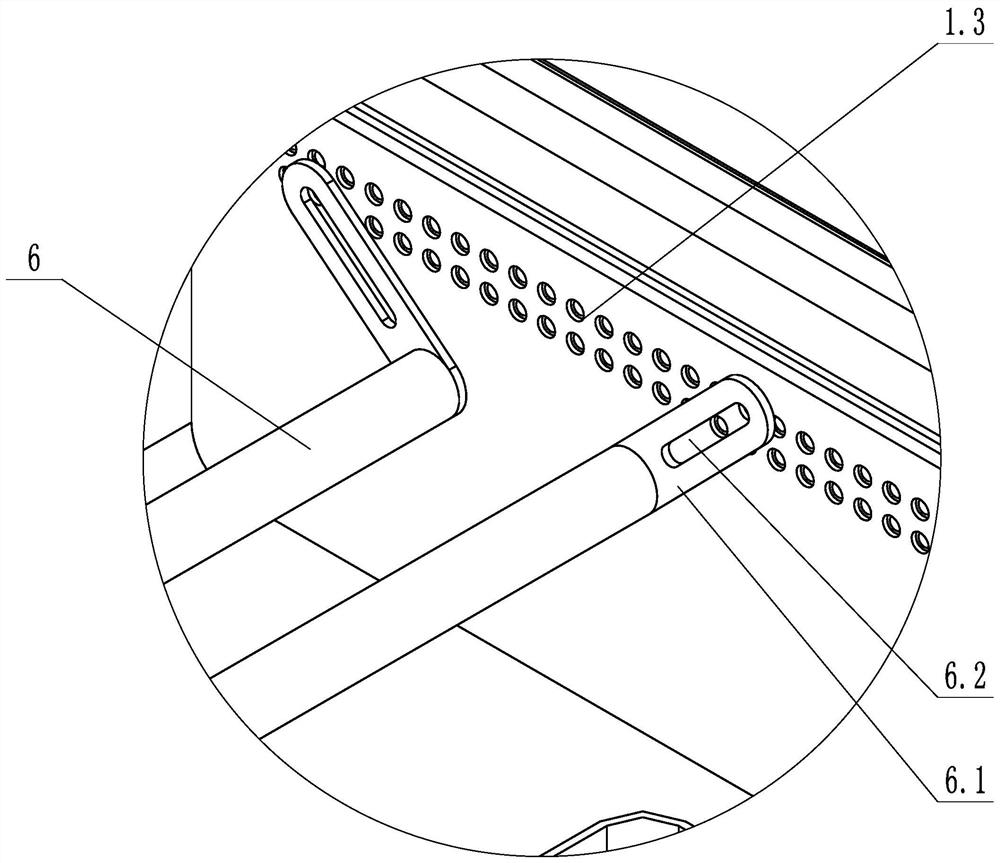
[0034] The middle position of the sink table 1 is provided with a water storage tank 1.1 for water storage; the inside of the water storage tank 1.1 is welded with a plurality of support tubes 1.2 along the X-axis direction, which are used to carry the cleaning basket 2 for stacking thermoelectric products, and have a certain distance from the bottom of the water storage tank 1.1. There is a positioning through hole near the operating end of the staff, and the fast positioning can be realized by inserting the bolt, such as figure 2 As shown, there are threaded holes 1.3 on both sides of the water storage tank 1.1, which are used to install the wire rod 6. The wire rod 6 is installed parallel to the inside of the sink table 1 along the Y-axis direction, a...

Embodiment 2

[0042] Such as Figure 4 As shown, on the basis of Embodiment 1, a waterproof structure 9 is also included. The waterproof structure 9 includes a protective cover 9.1, and the protective cover 9.1 is arranged above the X-axis driving structure 4. There is a strip avoidance hole 9.1.1, and one end of the bridge connecting plate 4.4 passes through the avoidance hole 9.1.1.

[0043] Such as Figure 5 As shown, the upper surface of the bridge connecting plate 4.4 is fixed with the first waterproof angle plate 9.2 and the third waterproof angle plate 9.4, and the lower surface of the bridge connecting plate 4.4 is fixed with the second waterproof angle plate 9.3 and the fourth waterproof angle plate 9.5 ; The first waterproof corner plate 9.2 and the second waterproof corner plate 9.3 are arranged on the outside of the protective cover 9.1, and the first waterproof corner plate 9.2 and the second waterproof corner plate 9.3 are arranged on the upper and lower corresponding positio...


PUM


Abstract

The invention discloses an automatic air jet type water removal cleaning device, comprising: a water tank table, which is provided with a water storage tank; a cleaning basket, which is used for placing thermoelectric products to be water removed, and the cleaning basket is arranged in the water storage tank; The jet structure is used for fast jetting and dewatering cleaning of the outer surface and cables of the thermoelectric product; the Y-axis driving structure is used for driving the jetting structure to move along the Y-axis, and the jetting structure is arranged on the Y-axis driving structure; the X-axis The driving structure is used for driving the Y-axis driving structure to move along the X-axis, and the Y-axis driving structure is arranged on the X-axis driving structure. The invention provides an automatic air jet type water removal and cleaning device, which has the advantages of high water removal and cleaning efficiency, wide application range, good feasibility, easy operation, strong function expansibility, and the like.

Description

technical field [0001] The invention relates to the field of development of thermoelectric product production equipment, in particular to an automatic jet-type water removal and cleaning device. Background technique [0002] After the wire bonding process, thermoelectric products need to be cleaned by water washing and jet water removal in order to remove water stains, welding slag and dirt on the inner and outer surfaces. The present invention is mainly aimed at the water removal and cleaning process after the water washing cleaning process. In view of the diversification of thermoelectric product specifications, the cleaning process, cleaning method, cleaning efficiency and automation of the cleaning process of thermoelectric products after the wire bonding process are all facing great challenges; at present, the cleaning process is completely done manually. There is also a lack of corresponding automation solutions and devices at home and abroad; therefore, in order to si...

Claims


Application Information

Patent Timeline
Patent Type & Authority Patents(China)
IPC IPC(8): B08B5/02B08B13/00
CPCB08B5/02B08B13/00
Inventor 吴樟伟吕庆鑫贾向军
Owner 浙江先导热电科技股份有限公司
Learn More