Eureka AIR delivers breakthrough ideas for toughest innovation challenges, trusted by R&D personnel around the world.

Airtight packaging structure of integrated thermoelectric refrigerator and preparation method thereof

A thermoelectric cooler and hermetic packaging technology, which is applied in the direction of electrical components, electric solid devices, circuits, etc., can solve the problems of affecting the overall heat dissipation capacity of the device, reducing the heat dissipation effect of TEC, increasing the thermal resistance of the interface, etc., and achieving the convenience of circuit interconnection And airtight welding, improve heat resistance, reduce the effect of thermal resistance

Active Publication Date: 2020-07-10
HUAZHONG UNIV OF SCI & TECH
View PDF3 Cites 3 Cited by
  • Summary
  • Abstract
  • Description
  • Claims
  • Application Information

AI Technical Summary

Problems solved by technology

The current technical solution is to weld the TEC inside the cavity of the LTCC substrate. The cold end is bonded to the chip to cool down, and the hot end is in contact with the ceramic base to achieve heat dissipation. Due to the limitations of welding materials and processes, the heat dissipation effect is poor.
If the TEC is welded outside the cavity of the LTCC substrate, that is, the lower end of the ceramic substrate, the heat generated by the chip must pass through the LTCC substrate to be conducted to the TEC, and more interfaces will reduce the heat dissipation effect of the TEC.
Therefore, whether the TEC is soldered inside or outside the cavity of the LTCC substrate, it will increase the interface thermal resistance and affect the overall heat dissipation capability of the device.

Method used


Image

  • Airtight packaging structure of integrated thermoelectric refrigerator and preparation method thereof
  • Airtight packaging structure of integrated thermoelectric refrigerator and preparation method thereof

Examples


preparation example Construction

[0029] The present invention also provides a method for preparing an airtight packaging structure of an integrated thermoelectric cooler, the preparation method comprising the following steps:

[0030] Step 1: providing a three-dimensional ceramic substrate, and preparing a thermoelectric cooler on the three-dimensional ceramic substrate, so that the three-dimensional ceramic substrate and the thermoelectric cooler share a ceramic substrate.

[0031] Step 2, installing the chip in the cavity of the three-dimensional ceramic substrate, and using the packaging cover plate for hermetic packaging, thereby obtaining the hermetic packaging structure of the integrated thermoelectric cooler.

Embodiment 1

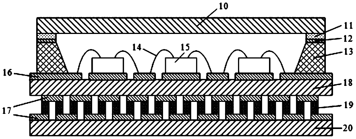
[0034] see figure 1 , the hermetic packaging structure of an integrated thermoelectric cooler provided in Embodiment 1 of the present invention, the hermetic packaging structure includes a packaging cover plate 10, a chip 15, a thermoelectric cooler and a three-dimensional ceramic substrate, and the thermoelectric cooler and the three-dimensional The ceramic substrates are connected, and the two share a ceramic substrate. The three-dimensional ceramic substrate is formed with a cavity, the chip 15 is disposed in the cavity, and the package cover 10 is connected to the three-dimensional ceramic substrate to package the chip 15 in the cavity.

[0035]In this embodiment, the ceramic substrate shared by the thermoelectric cooler and the three-dimensional ceramic substrate is the TEC upper substrate 18 . The TEC upper substrate 18 is directly bonded to the chip 15 . The thermoelectric cooler includes a TEC graphic layer 17, a PN type refrigeration element 19 and a TEC lower subst...

Embodiment 2

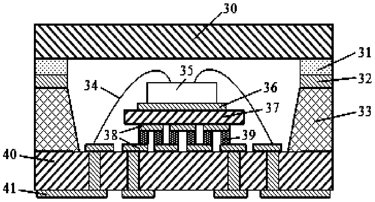
[0052] see figure 2 , the hermetic packaging structure of the integrated thermoelectric cooler provided by Embodiment 2 of the present invention, the hermetic packaging structure includes a packaging cover plate 30, a chip 35, a thermoelectric cooler and a three-dimensional ceramic substrate, and the thermoelectric cooler and the three-dimensional The ceramic substrates are connected, and the two share a ceramic substrate. The three-dimensional ceramic substrate is formed with a cavity, the chip 35 is disposed in the cavity, and the package cover 30 is connected to the three-dimensional ceramic substrate to package the chip 35 in the cavity.

[0053] In this embodiment, the ceramic substrate shared by the thermoelectric cooler and the three-dimensional ceramic substrate is the TEC lower substrate 40 . The thermoelectric cooler also includes a TEC upper substrate 37, two TEC graphic layers 38 and a plurality of PN type cooling elements 39, the TEC lower substrate 40 is in con...


PUM

PropertyMeasurementUnit
thicknessaaaaaaaaaa
thicknessaaaaaaaaaa
thicknessaaaaaaaaaa

Abstract

The invention belongs to the related technical field of microelectronic packaging, and discloses an airtight packaging structure of an integrated thermoelectric refrigerator and a preparation method thereof. The airtight packaging structure of the integrated thermoelectric refrigerator comprises a packaging cover plate, a chip, the thermoelectric refrigerator and a three-dimensional ceramic substrate, a cavity is formed in the three-dimensional ceramic substrate, the chip is arranged in the cavity, and the packaging cover plate is in airtight connection with the three-dimensional ceramic substrate so as to package the chip in the cavity; the three-dimensional ceramic substrate is connected with the thermoelectric refrigerator, and the three-dimensional ceramic substrate and the thermoelectric refrigerator share one ceramic substrate, so that the heat dissipation refrigerator and the three-dimensional ceramic substrate are combined to form an airtight packaging structure. According to the airtight packaging structure, the three-dimensional DPC ceramic substrate is used, and interconnection between the inside and the outside of the cavity is realized by utilizing the cavity structureand the vertical interconnection characteristic of the three-dimensional DPC ceramic substrate; the three-dimensional DPC ceramic substrate is used as a ceramic substrate of the TEC, that is, the thermoelectric refrigerator and the three-dimensional ceramic substrate share the ceramic substrate, so that one layer of ceramic substrate and one layer of welding interface are reduced, the heat dissipation capability of the device is improved, the thermal resistance can be reduced, and the packaging integration degree is improved.

Description

technical field [0001] The invention belongs to the related technical field of microelectronic packaging, and more specifically relates to an airtight packaging structure of an integrated thermoelectric cooler and a preparation method thereof. Background technique [0002] With the development of technology and the continuous extension of application requirements, the third-generation semiconductor materials represented by SiC and GaN are widely used in aerospace, weapons, etc. Equipment, automotive electronics and other fields have important application value. Chip packaging is also gradually tending to miniaturization, high integration, high reliability, high power density and other excellent electrical and mechanical properties. Since electronic devices in these fields have been in harsh environments such as high temperature, high humidity, and large temperature changes for a long time, more stringent requirements have been put forward for the heat dissipation and servic...

Claims


Application Information

Patent Timeline
Patent Type & Authority Applications(China)
IPC IPC(8): H01L25/16H01L23/31H01L23/38
CPCH01L25/16H01L25/165H01L23/3121H01L23/38H01L2224/48227H01L2224/48091H01L2924/16195H01L2924/00014
Inventor 陈明祥刘佳欣黎双
Owner HUAZHONG UNIV OF SCI & TECH
Why Eureka
Eureka Blog
Learn More