
Patsnap Eureka
For R&D, Patsnap Eureka makes reading and utilizing patents & technical documents easy.
Patsnap Eureka AIR
Designed for self-driven R&D workflows. Generate viable solutions, solve complex R&D challenges, empower your innovation with AI.

Patsnap Eureka Materials
Designed for material experts only. Revolutionize your material R&D, from search, analyze, to developing new materials.

TechResearch
Generate reliable direction feasibility study reports for your R&D in just a few steps.

TechSeek
Discover and master advanced knowledge NOW. Basics, ideas, possibilities, all at once.

TechMind
As an expert in R&D Theories, TechMind can generates customized viable solutions instantly.

TechRisk
Analyze your overall solution with one click, know your potential R&D risks in advance.

TechMonitor
Get weekly tech updates, stay abreast of the latest tech innovations and key insights.
High-temperature oil treatment device for capacitor processing
A capacitor processing and processing device technology, which is applied in the direction of capacitors, capacitor manufacturing, and winding capacitor machines, can solve the problems of long processing time, low processing index, and high cost, so as to improve the processing effect, ensure uniform oiling, and improve The effect of cooling effect
- Summary
- Abstract
- Description
- Claims
- Application Information
AI Technical Summary
Problems solved by technology
Method used
Image


Examples
Embodiment 1
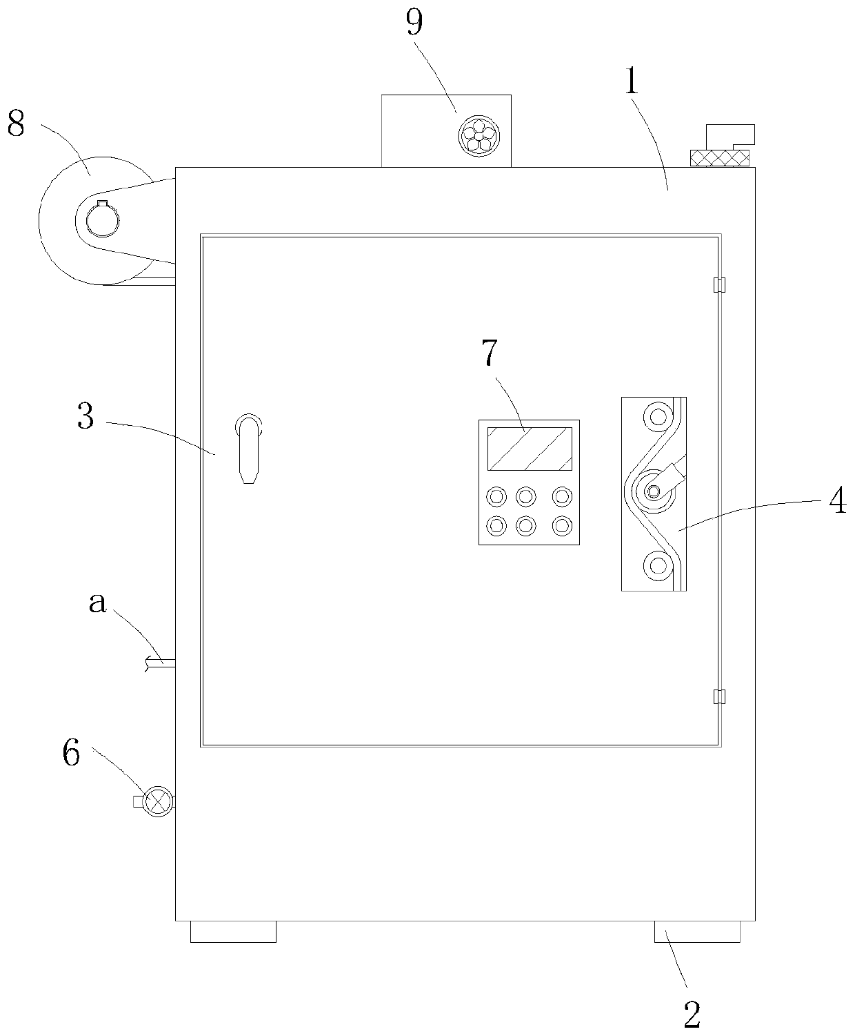
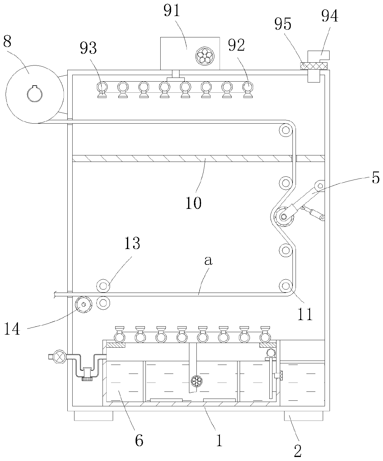
[0037] A high-temperature oil treatment device for capacitor processing, comprising a device outer box 1, a plurality of support feet 2 installed at the lower end of the device outer box 1, and a box door 3 installed on the front wall of the device outer box 1, the side of the device outer box 1 A film inlet and a film outlet matching the capacitor metallized film a are opened on the wall in sequence from bottom to top, and a winding roller 8 is arranged outside the film outlet, and the winding roller 8 is detachably installed in the outer box of the device through a rotating bracket 1, and the rear end of the winding roller 8 is installed on the input end of the winding motor 12, and the winding motor 12 is installed on the rotating bracket, and the winding roller 8 is driven by the winding motor 12 to wind The capacitor metallized film a is used as the power to pull the capacitor metallized film a to ensure the continuous high-temperature oil treatment of the capacitor metall...
Embodiment 2
[0048] The difference between this embodiment and embodiment 1 is that, as Figure 4 As shown, the oil rolling mechanism 5 is provided downstream of the oiling mechanism 6, and the oil rolling mechanism 5 includes a rolling oil roller brush 51 whose annular side wall is pasted on the capacitor metallized film a, and the oil rolling brush 51 is installed on On the turret 52, a mounting rod 53 is vertically installed on the turret 52, and the other end of the mounting rod 53 is installed on the inner wall of the device outer box 1 through the hinge seat I54, and the side wall of the mounting rod 53 is hinged with an electric push rod 55, And the other end of the electric push rod 55 is installed on the inner wall of the device outer box 1 through the hinge seat II5, and the roller brush 51 resists the metallized film a of the capacitor, and rotates along with the operation of the metallized film a of the capacitor, effectively turning the metallized film a The oil sprayed on the...
PUM
 Abstract
Description
Claims
Application Information
 - R&D Engineer
- R&D Manager
- IP Professional
- Industry Leading Data Capabilities
- Powerful AI technology
- Patent DNA Extraction
Browse by: Latest US Patents, China's latest patents, Technical Efficacy Thesaurus, Application Domain, Technology Topic, Popular Technical Reports.
© 2024 PatSnap. All rights reserved.Legal|Privacy policy|Modern Slavery Act Transparency Statement|Sitemap|About US| Contact US: help@patsnap.com