
Screw excited hydraulic harmonic high-power enhancement vibrator

A vibrator and screw technology, applied in the direction of drilling with vibration, can solve the problems affecting the speed and cost of oilfield exploration and development, increase in drilling cost, lack of vibration power, etc. , The effect of simple and compact structure

Pending Publication Date: 2020-07-10
YANGTZE UNIVERSITY
View PDF0 Cites 3 Cited by
  • Summary
  • Abstract
  • Description
  • Claims
  • Application Information

AI Technical Summary

Problems solved by technology

Among them, some unconventional wells have poor drillability due to the tight formation lithology. When drilling with conventional drilling methods, the drilling cycle is long and there are many complicated situations encountered in the drilling process. Due to the high friction between the drill pipe and the borehole wall due to the combination and low efficiency of cuttings return, there is a back pressure phenomenon, which reduces the transmission efficiency of drilling pressure, reduces the horizontal drilling length and drilling speed, and easily causes sticking Waiting for the occurrence of underground complex accidents
This leads to a sharp increase in drilling costs, which directly affects the speed and cost of oilfield exploration and development
In order to solve the above problems, a hydraulic oscillator is usually installed on the tool string, and the installed hydraulic oscillator can generate periodic pulse vibrations, which can well reduce friction and improve drilling efficiency; but due to Due to the structural reasons of the existing hydraulic oscillator, the vibration power is lacking, which cannot completely solve the problems of friction and pressure between the drill pipe and the well wall, so it is necessary to improve it

Method used


Image

  • Screw excited hydraulic harmonic high-power enhancement vibrator
  • Screw excited hydraulic harmonic high-power enhancement vibrator
  • Screw excited hydraulic harmonic high-power enhancement vibrator

Examples


Embodiment Construction

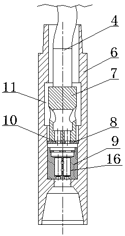
[0022] The hydraulic harmonic high-amplification enhanced vibrator excited by the screw includes a vibrator body 1 and a screw power sub-joint 2; the screw power sub-joint 2 is composed of a sub-joint housing 3 and a screw rotor 4 and a screw stator 5 inside the sub-joint housing 3 , The vibrator body 1 and the screw power nipple 2 are screwed together. The vibrator body 1 is composed of a vibrator shell 6, a screw rotor head 7, a fixed cut-off block 8 and a resonance reinforcement 9; It is a circular plate-shaped body, and the central part of the fixed cut-off block 8 is provided with an overflow hole 10 corresponding to the flow channel hole 12 of the pulse nozzle.

[0023] A pulse chamber 11 is provided in the stepped through hole above the fixed cut-off block 8, and a screw rotor head 7 is installed in the pulse chamber 11. The screw rotor head 7 is cylindrical, and the middle part of the screw rotor head 7 is provided with a confluence chamber 20 for converging flow. The...


PUM


Abstract

The invention relates to a screw excited hydraulic harmonic high-power enhancement vibrator, and belongs to the technical field of petroleum and natural gas extraction downhole tools. The vibrator comprises a vibrator body and a screw power short joint. The vibrator body is composed of a vibrator shell, a screw rotor head, a fixed closure block and a resonance enhancement part. The fixed closure block is mounted in the vibrator shell, and the resonance enhancement part is mounted below the fixed closure block. The screw rotor head is mounted above the fixed closure block. By means of the vibrator, wear and resistance reduction between a drill rod and the well wall can be achieved, high-pressure well drilling fluid completing impacting on a screw rotor enters the resonance enhancement part,and therefore the Helmholtz effect is formed, the pulsation effect of the high-pressure well drilling fluid is enhanced and amplified with high power, pipe bundle wriggling is caused by axial pulsation generated by the above process, the pressure transmission efficiency is higher by means of double force cooperation, and the back pressure relief effect is better. The problem that due to the structure of an existing hydraulic vibrator, friction and resistance and back pressure existing between the drill rod and the well wall cannot be solved thoroughly is solved.

Description

technical field [0001] The invention relates to a hydraulic harmonic high-magnification enhanced vibrator excited by a screw, which belongs to the technical field of downhole tools for oil and natural gas exploitation. Background technique [0002] As the drilling depth continues to increase, the well depth structure becomes more complex, and the number of long-horizontal, highly-inclined, and multi-branch horizontal wells has become increasingly prominent. The exploration and development of oil and gas resources in my country has entered an era of difficult exploitation. [0003] In the current engineering, the above-mentioned complex oil and gas wells are classified as unconventional oil and gas resources. Among them, some unconventional wells have poor drillability due to the tight formation lithology. When drilling with conventional drilling methods, the drilling cycle is long and there are many complicated situations encountered in the drilling process. Due to the high...

Claims


Application Information

Patent Timeline
IPC IPC(8): E21B7/24
CPCE21B7/24
Inventor 易先中刘航铭周元华
Owner YANGTZE UNIVERSITY
Learn More