
Paper product container processing method

A processing method and technology of paper products, applied in the fields of metal processing, textiles and papermaking, etc., can solve the problems of irrationality, long distribution of production lines, and low processing efficiency of paper products

Active Publication Date: 2020-07-10
ZHEJIANG SHURCON MFG
View PDF9 Cites 1 Cited by
  • Summary
  • Abstract
  • Description
  • Claims
  • Application Information

AI Technical Summary

Problems solved by technology

[0003] Due to the long production line and the unreasonable structure and distribution of each processing unit in the current paper product production line, the paper product processing efficiency is low

Method used


Image

  • Paper product container processing method
  • Paper product container processing method
  • Paper product container processing method

Examples


Embodiment 1

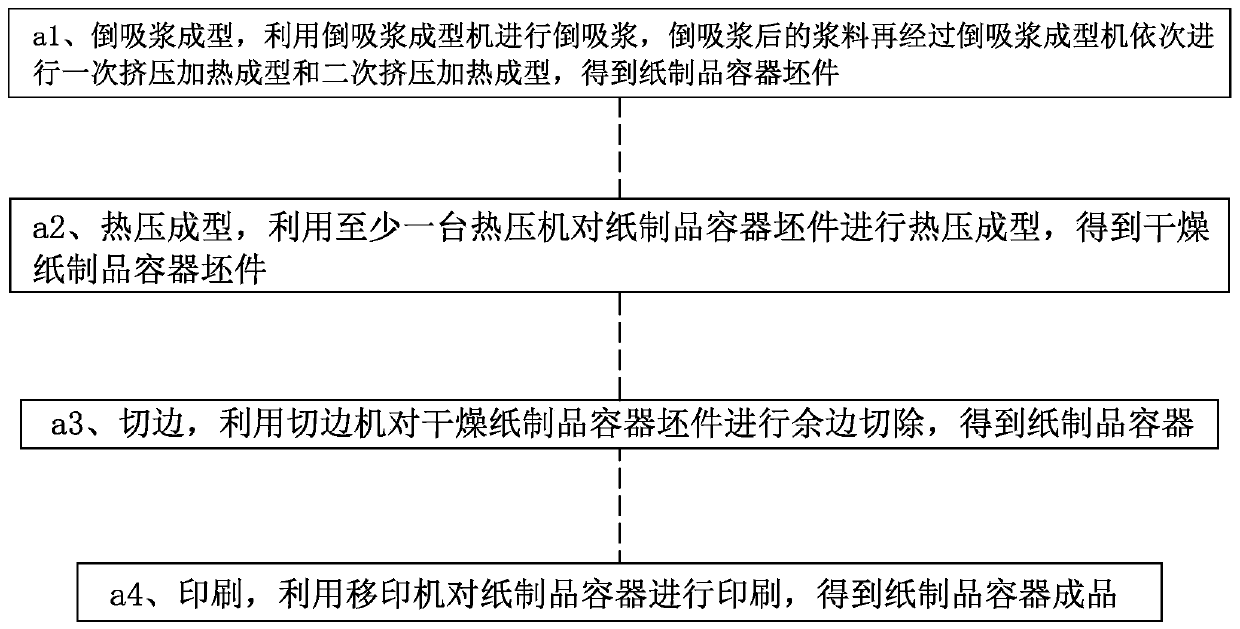
[0118] Such as figure 1 with figure 2 Shown, this a kind of paper product container processing method comprises the steps:

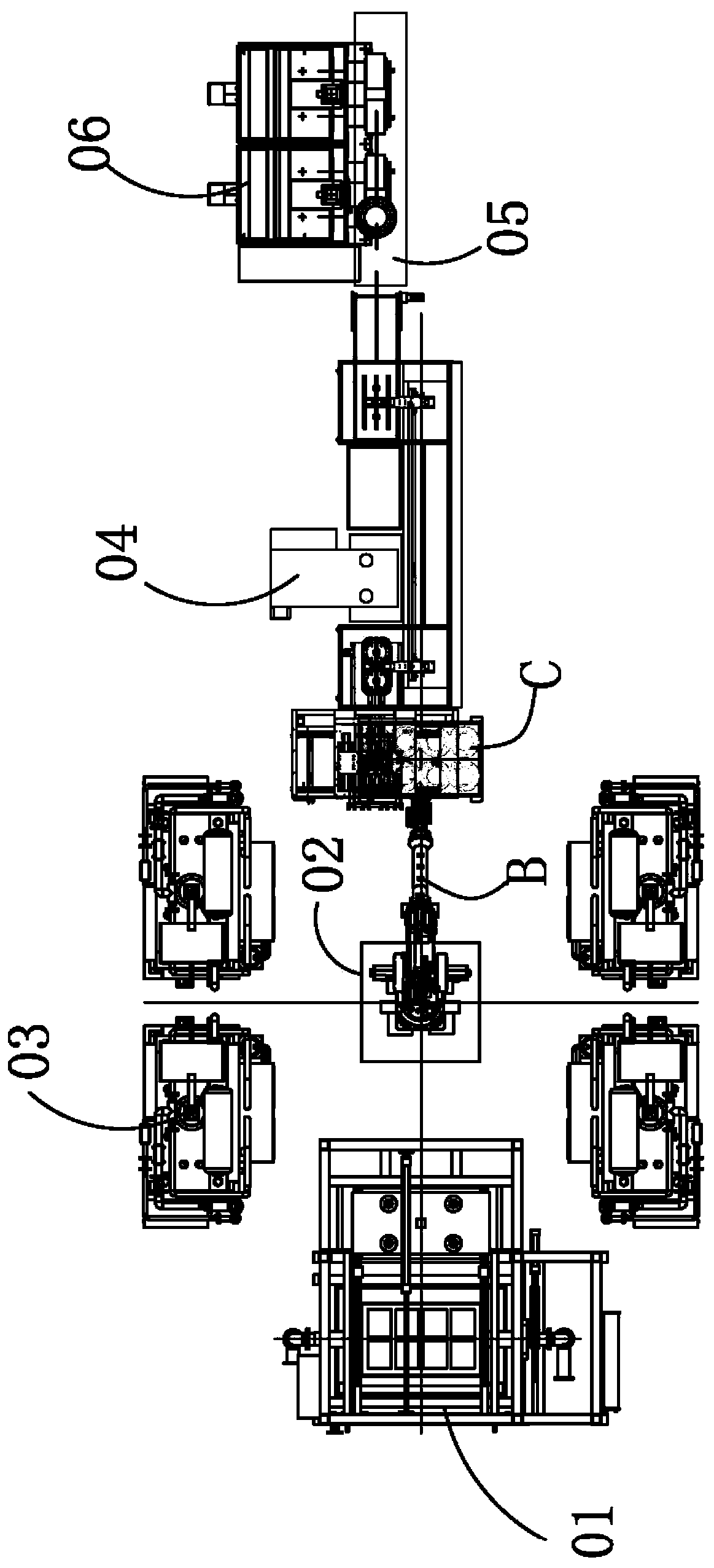
[0119] a1. Slurry forming, using Slurry Forming Machine 01 to perform Slurry Slurry, the slurry after Slurry Slurry is then subjected to primary extrusion heating molding and secondary extrusion heating molding through the Slurry Slurry Forming Machine to obtain paper Product container blanks;

[0120] The heating of the extrusion belt can not only shorten the subsequent hot press molding time, but also facilitate the transfer of the blank.

[0121] Further, the temperature of the primary extrusion thermoforming is lower than the temperature of the secondary extrusion thermoforming.

[0122] The temperature difference and the gradual increase design can preheat the wet billet and heat it after preheating to ensure product quality.

[0123] The number of suction pulp forming machine 01 can be set according to the actual production capacity, for examp...

Embodiment 2

[0268] The structure and principle of this embodiment are the same as that of Embodiment 1, the difference is that: the suction pulp forming machine, the mechanical transfer device and the trimming machine are located on the same straight line, and the total number of the hot presses is 1-8 Taiwan, and the hot press is distributed on either side of the same straight-line suction pulp forming machine and / or mechanical transfer device.

Embodiment 3

[0270] The structure and principle of this embodiment are the same as those of Embodiment 1, the difference lies in:

[0271] Such as Figure 14 Shown, wet base transfer mold C1 comprises base plate-C11, is provided with 1-12 vacuum-pumping hole-C12 on base plate-C11, is provided with wet base form C13 at the side of base plate-C11 away from product transfer mold C2, in wet The side of the base mold C13 near the base plate C11 is provided with an air chamber C14 equal in number to the vacuum hole C12 and one air chamber C14 communicates with a vacuum hole C12, on the side of the wet blank mold C13 away from the base plate C11 The above-mentioned wet billet adsorption pockets C10 are provided. The number of wet billet adsorption pockets C10 is equal to the number of air chambers C14, and each wet billet adsorption recess C10 communicates with an air chamber C14 through several air-permeable small holes C15.


PUM


Abstract

A paper product container processing method comprises the following steps: a1, suck-back pulp forming is conducted, specifically, pulp suck-back is carried out by using a suck-back pulp forming machine, and pulp subjected to pulp suck-back is sequentially subjected to primary extrusion heating forming and secondary extrusion heating forming by using the suck-back pulp forming machine, so that a paper product container blank is obtained; a2, hot press molding is conducted, specifically, at least one hot press is used for conducting hot press molding on the paper product container blank, and a dry paper product container blank is obtained; a3, edge cutting is conducted, specifically, residual edges of the dried paper product container blank are cut off through an edge cutting machine, and apaper product container is obtained; and a4, printing is conducted, specifically, the paper product container is printed by using a pad printing machine to obtain a finished product of the paper product container.

Description

technical field [0001] The invention belongs to the technical field of plant fiber product processing, and in particular relates to a method for processing paper product containers. Background technique [0002] Pulp molded products can be called paper product containers, such as cup lids and cups, etc. Pulp molded products formed by extrusion and hot pressing need to cut off the reserved margins. When cutting, special molds are generally used for trimming. [0003] Due to the long production line and the unreasonable structure and distribution of each processing unit in the current paper product production line, the paper product processing efficiency is low. Contents of the invention [0004] The object of the present invention is to address the above problems and provide a method for processing paper product containers that can solve the above technical problems. [0005] To achieve the above object, the present invention adopts the following technical solutions: [...

Claims


Application Information

Patent Timeline
IPC IPC(8): D21J3/00D21J3/10D21J3/12B26D7/00B26D7/26B26F1/38B26F1/44
CPCB26D7/00B26D7/26B26D2007/0018B26D2007/2607B26F1/38B26F1/44D21J3/00D21J3/10D21J3/12
Inventor 潘耀华胡峻珲岑刚王楷胡庆军
Owner ZHEJIANG SHURCON MFG
Learn More