Clamp for large spherical casting multi-hole multi-plane same-direction machining

A large-scale casting, multi-plane technology, applied in the direction of manufacturing tools, metal processing equipment, metal processing machinery parts, etc., can solve the problems of waste of manpower, unstable clamping, long processing period, etc., to avoid uneven force, shorten Processing cycle, the effect of ensuring processing quality

Active Publication Date: 2015-11-18
ANHUI YONGCHENG MACHINERY
View PDF7 Cites 2 Cited by
  • Summary
  • Abstract
  • Description
  • Claims
  • Application Information

AI Technical Summary

Problems solved by technology

[0002] Large-scale parts, especially long and irregular large-scale castings after casting, need to be finished with multiple surfaces or multiple installation positions after casting to meet the local functionality and connectivity of large-scale castings. Requirements, but especially for large castings with many curved surfaces and complex surface shapes, in the finishing process, whether it is positioning or processing after positioning, the operation requires the cooperation of multiple people at the same time, and each surface and each A part of the processing must be fixed separately, which makes the processing period longer and wastes manpower. During processing, there will also be a phenomenon of knife vibration, which will affect the local dimensional accuracy of the large casting to be processed. In severe cases, it will cause scrapping and positioning. The accuracy is not good
And each positioning may require different fixtures, and the cost is relatively high
[0003] For large spherical parts or castings, when clamping, due to the unstable clamping, it will cause the phenomenon of knife vibration of the processed parts, resulting in insufficient surface finish of the processed parts and accurate processing dimensions.

Method used


Image

  • Clamp for large spherical casting multi-hole multi-plane same-direction machining
  • Clamp for large spherical casting multi-hole multi-plane same-direction machining
  • Clamp for large spherical casting multi-hole multi-plane same-direction machining

Examples


Embodiment Construction

[0018] In order to deepen the understanding of the present invention, the present invention will be further described below in conjunction with the accompanying drawings and embodiments, which are only used to explain the present invention and do not limit the protection scope of the present invention.

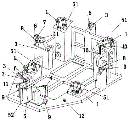
[0019] Such as figure 1 As shown, the jig for large-scale spherical casting porous multi-plane processing with the same orientation includes a V-shaped support body 5 arranged on the skeleton, and at least three angle supports 3 alternately arranged between the support seat 51 and the end support seat 52 The V-shaped support body 5 includes at least two groups of respectively symmetrical support seats 51, and an end support seat 52 which is arranged on the symmetrical axis of the two groups of respectively symmetrically arranged support seats 51 and is located at one end thereof, and each group of mutually symmetrical The heights of the support bases 51 are the same, but the h...


PUM


Abstract

The invention discloses a clamp for large spherical casting multi-hole multi-plane same-direction machining. The clamp comprises a V-shaped supporting body arranged on a framework, and at least three angle supports arranged between supporting bases and end supporting bases in a staggered manner. The V-shaped supporting body comprises at least two sets of symmetric supporting bases and end supporting bases, wherein the end supporting bases are arranged on the symmetry axis of the two sets of symmetrically-arranged supporting bases and located at one ends of the supporting bases. The end supporting bases and the supporting bases are each provided with a clamping pawl. Each angle support is provided with a supporting nail. The clamp is simple in structure, low in cost and high in clamping stability. The integral strength and rigidity of the clamp are guaranteed, and the phenomenon of cutter vibration generated during cutting of a to-be-machined large spherical casting or other large spherical components is avoided. The smoothness of workpiece machining surfaces and the precision of machining sizes are improved, and the production machining quality of products is improved.

Description

technical field [0001] The invention relates to the technical field of large parts, especially large castings, in particular to a jig for processing porous and multi-plane same-direction processing of large spherical castings. Background technique [0002] Large-scale parts, especially long and irregular large-scale castings after casting, need to be finished with multiple surfaces or multiple installation positions after casting to meet the local functionality and connectivity of large-scale castings. Requirements, but especially for large castings with many curved surfaces and complex surface shapes, in the finishing process, whether it is positioning or processing after positioning, the operation requires the cooperation of multiple people at the same time, and each surface and each A part of the processing must be fixed separately, which makes the processing period longer and wastes manpower. During processing, there will also be a phenomenon of knife vibration, which wi...

Claims


Application Information

Patent Timeline
Patent Type & Authority Applications(China)
IPC IPC(8): B23Q3/06
CPCB23Q3/062
Inventor 章步青
Owner ANHUI YONGCHENG MACHINERY
Why Eureka
Try Eureka