Door Closing Unit

A technology of door closers and components, which is applied in door/window accessories, fastening devices for wing leaves, fastening devices for buildings, etc., and can solve problems such as complex valve systems

Active Publication Date: 2015-07-01
GEZE GMBH
View PDF5 Cites 1 Cited by
  • Summary
  • Abstract
  • Description
  • Claims
  • Application Information

AI Technical Summary

Problems solved by technology

Also, complex valve systems and valves are required to enable full hydraulic positioning
[0005] Electrohydraulic positioning requir

Method used


Image

  • Door Closing Unit
  • Door Closing Unit
  • Door Closing Unit

Examples


Embodiment Construction

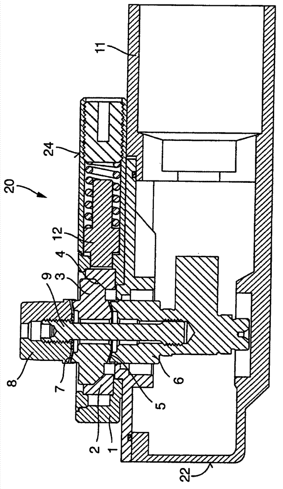
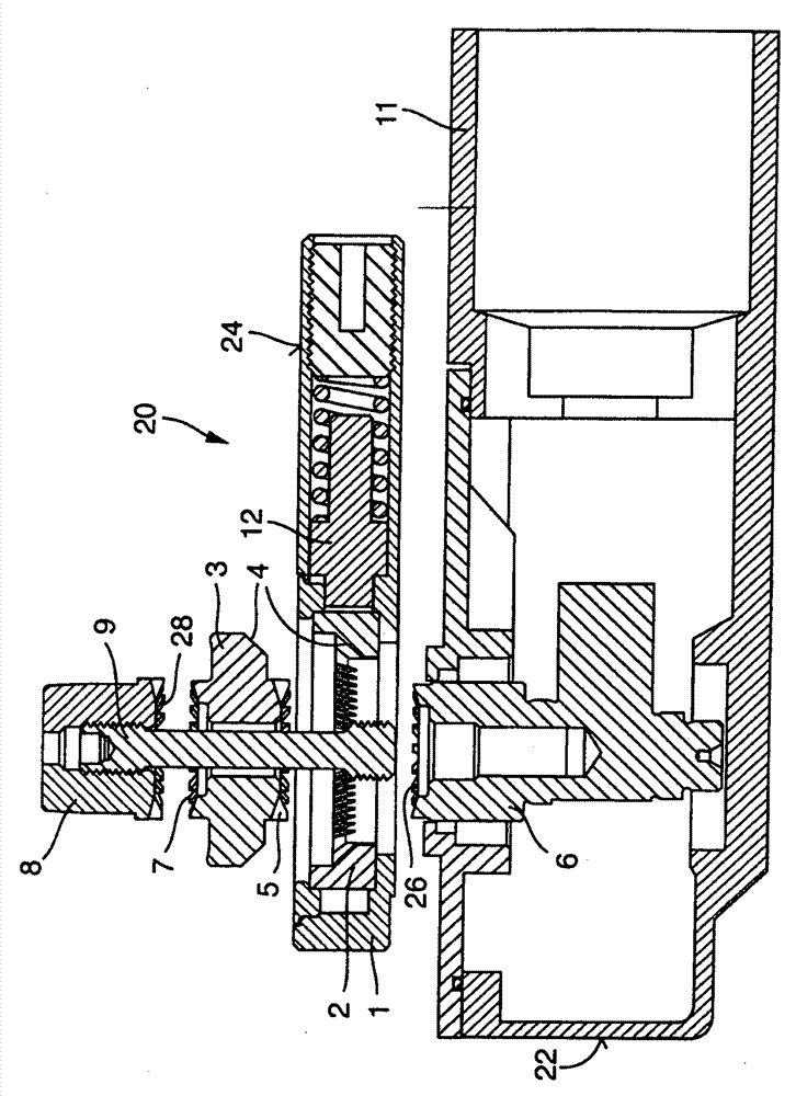
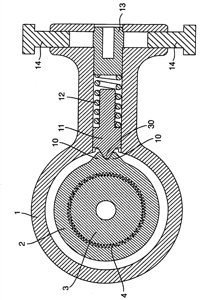
[0030] Figures 1 to 5 Shows a schematic diagram of an exemplary embodiment of a door closer unit 20 with a door closer 22 , an in particular plate-shaped adapter 24 that can be mounted on the door closer 22 and a two-part door closer A door closer shaft 6, 8, which in the present case is for example a ground door closer, said door closer shaft 6, 8 comprising a first door closer shaft part 6 and a second door closer shaft part Two door closer shaft parts 8 .

[0031] Here, the second closer shaft part 8 can be coupled to the first closer shaft part 6 via the shaft seat 3 which is supported in the housing 1 of the adapter 24 , wherein the respective door closer shaft parts 6 , 8 are respectively provided with teeth. Sections 26, 28 (see especially figure 2 ), the tooth parts 26 and 28 of the door closer shaft parts 6 and 8 cooperate with the tooth parts 5 and 7 of the shaft seat 3 respectively, so the first door closer shaft part 6 and the second door closer shaft part 8 ca...


PUM


Abstract

The present invention relates to a door closing unit. The door closing unit comprises a door closing device, an adapter arranged on the door closing device, and a door closing device shaft with multiple parts. The door closing device, especially a ground door closing device, comprises a first door closing device shaft part and a second door closing device shaft part which support the door closing device, and the second door closing device shaft part can be coupled with the first door closing device shaft part via a shaft base supporting in a shell of the adapter, wherein the door closing device shafts are respectively equipped with teeth matching the shaft base separately, so that the first and second door closing device shafts can be fixed at the different rotation positions relative to each other.

Description

technical field [0001] The invention relates to a door closing unit having a door closer, in particular a floor door closer, and an adapter which can be mounted on the door closer. Background technique [0002] Door closers are known, for example, in the form of top door closers or floor door closers and are used to automatically reclose a door leaf after the door has been opened and then released. [0003] The hitherto known floor door closers include different variants with mechanical, hydraulic or electrohydraulic positioning devices. The mechanical fixings alone include many different configurations, resulting in a large number of door closer shaft and door closer solutions. [0004] In hydraulic positioning devices, particularly complex measures have to be taken in order to keep the failure angle (Durchfallwinkel) of the relevant door as small as possible and thus to achieve the desired fixing of the door at the angle. Furthermore, complex valve systems and valves are...

Claims


Application Information

Patent Timeline
IPC IPC(8): E05F3/22E05C17/02
CPCE05Y2600/324E05Y2201/706E05F3/225E05Y2800/20E05Y2201/236E05Y2900/132E05Y2201/218E05Y2800/205E05Y2600/10
Inventor B·韦尔纳
Owner GEZE GMBH
Why Eureka
Try Eureka