wireless charging device

A technology of wireless charging and charging board, which is applied in the direction of circuit devices, battery circuit devices, current collectors, etc., and can solve problems such as inability to ensure charging behavior, inconvenience, human error, etc.

Active Publication Date: 2018-04-13
SPI ELECTRONICS
View PDF3 Cites 1 Cited by
  • Summary
  • Abstract
  • Description
  • Claims
  • Application Information

AI Technical Summary

Problems solved by technology

However, the user needs to manually align the two components, and then let the mobile terminal be absorbed on the wireless charging board, which is not only inconvenient to use, but also has human error, and cannot ensure the integrity of the charging behavior
In addition, different sizes of mobile terminals require different sizes of the clamping frame. If the mold is customized to make the clamping frame according to various mobile terminals, the cost will increase.
[0005] Furthermore, for the wireless charging device for vehicles, if the user needs to adjust / flip the screen angle for various purposes (such as watching movies, navigating, etc.) Both methods are inconvenient to adjust the positioning angle of the mobile terminal again after positioning the mobile terminal for the first time to match the visual angle required by the user

Method used


Image

  • wireless charging device
  • wireless charging device
  • wireless charging device

Examples


Embodiment Construction

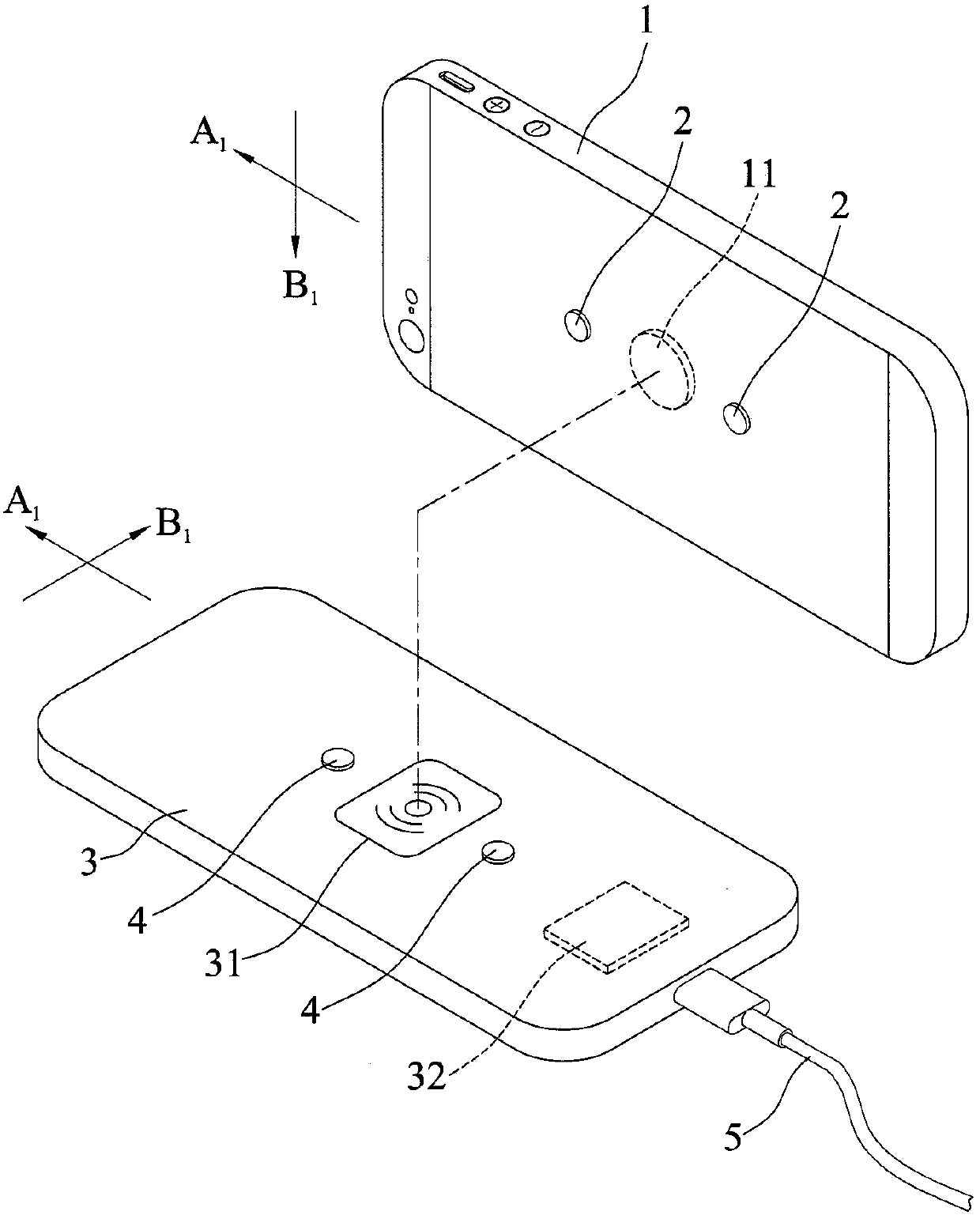
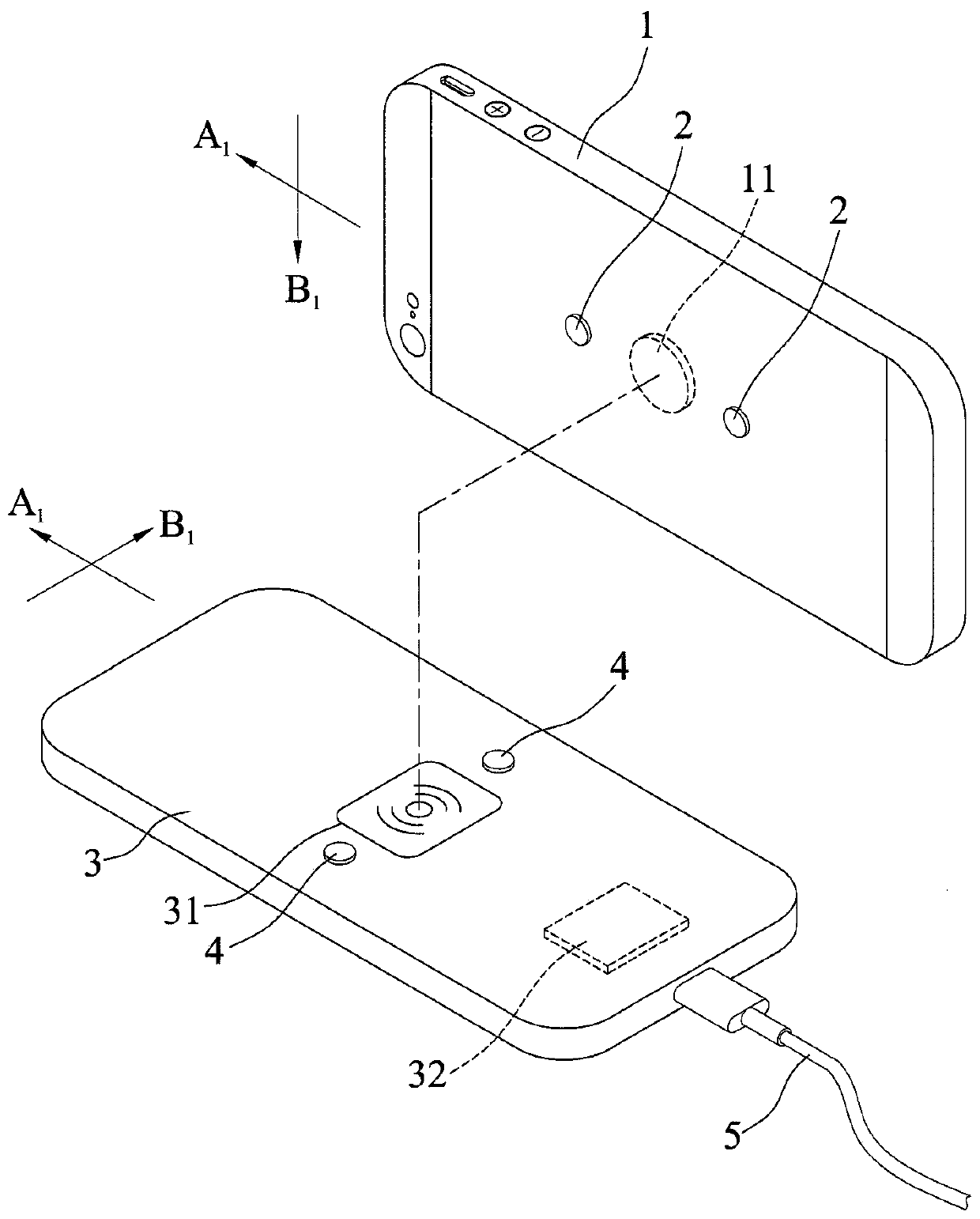
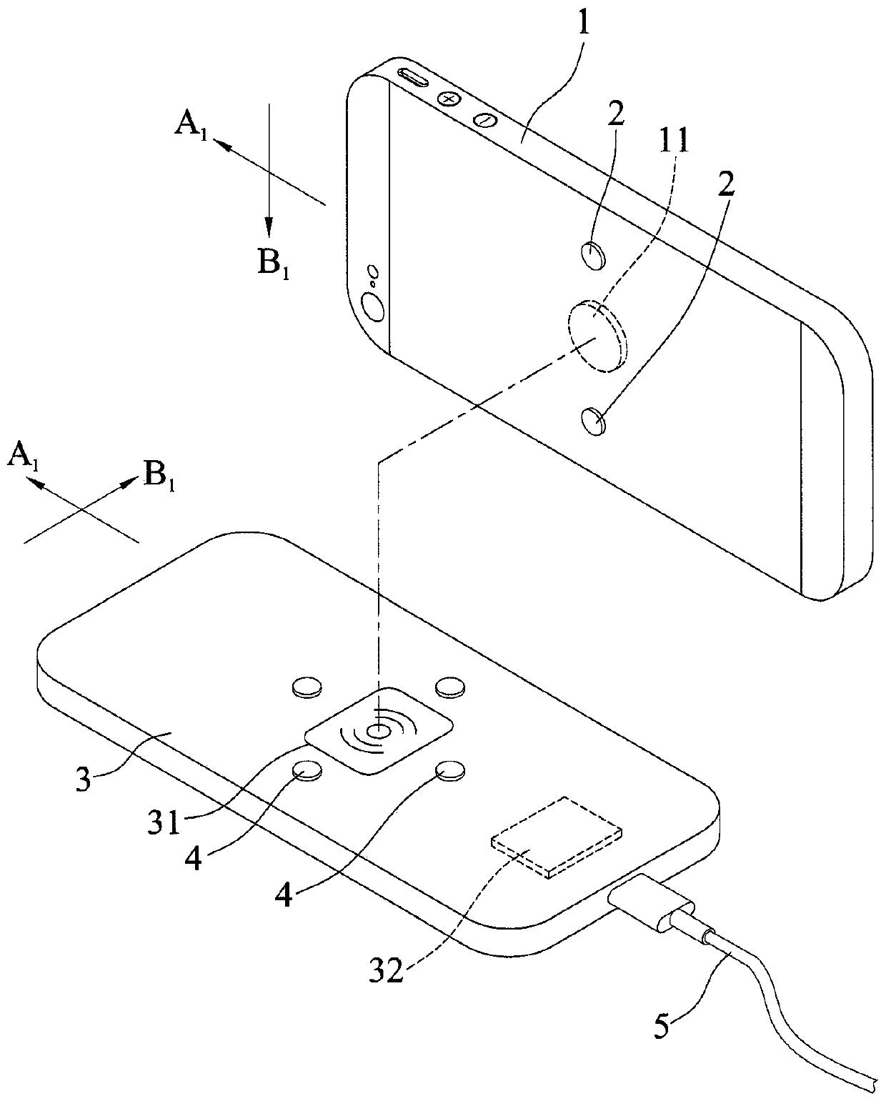
[0052] In order to make the content disclosed in the present invention more understandable, the following specific embodiments are taken as examples that the disclosure of the present invention can actually be implemented. In addition, wherever possible, components / members / steps with the same reference numerals are used in the drawings and embodiments to represent the same or similar parts.

[0053] refer to Figure 1 to Figure 4 , the present invention discloses a wireless charging device for wirelessly charging a mobile terminal 1, the mobile terminal 1 includes a receiving component 11 and is provided with a plurality of first magnetic bodies 2, and the plurality of first magnetic bodies 2 are configured as at least in a first direction A 1 There are two first magnetic bodies 2 to surround the receiving component 11 together, wherein the mobile terminal 1 can be a mobile phone or a tablet computer.

[0054] The wireless charging device includes a charging board 3 , a plur...


PUM


Abstract

The invention discloses a wireless charging device, which is used to wirelessly charge a mobile terminal. The mobile terminal includes a receiving component and is provided with a plurality of first magnetic bodies. There are two first magnetic bodies in the direction to surround the receiving component together. The wireless charging device includes a charging board carrying a mobile terminal and a plurality of second magnetic bodies arranged on the charging board, wherein the charging board includes a transmitting component for transmitting energy to a receiving component of the mobile terminal, and a plurality of second magnetic bodies The body is at least correspondingly attracted to the two first magnetic bodies, so that the receiving component is aligned with the sending component. The wireless charging device of the present invention can easily position the mobile terminal on the wireless charging device by virtue of the adsorption relationship between the first magnetic body and the second magnetic body without additionally passing through a suction cup or an engaging frame, and can be adjusted according to user needs. to adjust the positioning angle of the mobile terminal.

Description

technical field [0001] The present invention relates to a charging device, in particular to a wireless charging device for wirelessly charging a mobile terminal. Background technique [0002] With the advancement of technology, electronic mobile terminals are becoming more and more popular, and the power supply for electronic mobile terminals is becoming more and more important. In addition to wired charging, wireless charging is also one of the trends. [0003] When the user wants to perform wireless charging, it is necessary to align the receiving component of the mobile terminal (Mobile Device) with the transmitting component of the wireless charging board (Base Station) to perform charging. If the two components are not aligned or deviate, the Cause poor charging effect. [0004] In order to align the two components of the mobile terminal and the wireless charging pad in the existing wireless charging device, a suction cup or an engaging frame is usually provided on the...

Claims


Application Information

Patent Timeline
Patent Type & Authority Patents(China)
IPC IPC(8): H02J7/00
Inventor 谢文森
Owner SPI ELECTRONICS
Why Eureka
Try Eureka