
Stripping and cutting device capable of accurately controlling stripping and cutting depth of cable insulation layer

A technology for cable insulation and precise control, which is applied to equipment for connecting/terminating cables, equipment for dismantling/armoring cables, etc. Improve the quality of production and processing, reduce the risk of damage and scrap, and reduce the difficulty of operation and labor intensity

Pending Publication Date: 2022-07-29
广西新南润电力科技有限公司 +1
View PDF0 Cites 2 Cited by
  • Summary
  • Abstract
  • Description
  • Claims
  • Application Information

AI Technical Summary

Problems solved by technology

At present, there are many problems in the devices used for stripping and cutting the cable insulation layer: 1. The existing devices have high requirements for the skills of the operators, and they must be practiced through repeated training. Some devices take a long time to install and debug before stripping and cutting cables. The clamping force, axial cutting depth, radial cutting depth, and cutting parallelism of the device need to be adjusted many times, and it can only be applied after passing the trial cutting test; 3 .The biggest problem with all the peeling and cutting devices currently in use is that the radial cutting depth cannot be accurately controlled. The depth of each rotary cut cannot be controlled. It is necessary to rely on the balance of the rotary cutting force applied by the operator to control the depth
Some peeling and cutting devices are also equipped with radial cutting adjustment devices, but the depth adjustment device has poor stability and is affected by the resistance of the cutting depth. It needs to be adjusted many times during the operation process, which affects the operation efficiency.
For the uneven radial cutting depth in the process of peeling and cutting the insulating layer, there will be the following problems: (1) If the thickness of each rotary cut is uneven or the depth of each rotary cut increases sequentially, after a certain number of turns Finally, the cutting knife is affected by the cutting thickness, and the resistance gradually increases, which will increase the surface roughness of the insulating layer, cause surface scratches or overcut marks, and bring a lot of workload to the polishing process of the insulating layer surface; (2 ) When the rotary cutting depth is too deep, the cutting end surface will form a large angle cutting slope, which brings great difficulty to the flatness trimming process of the cable end surface; (3) the cutting depth cannot be controlled, resulting in the required The length dimension cannot be guaranteed. Once the length tolerance exceeds the allowable range, the produced cable joint size is unqualified and needs to be reworked. Repeated failures will cause the cable to be scrapped.

Method used

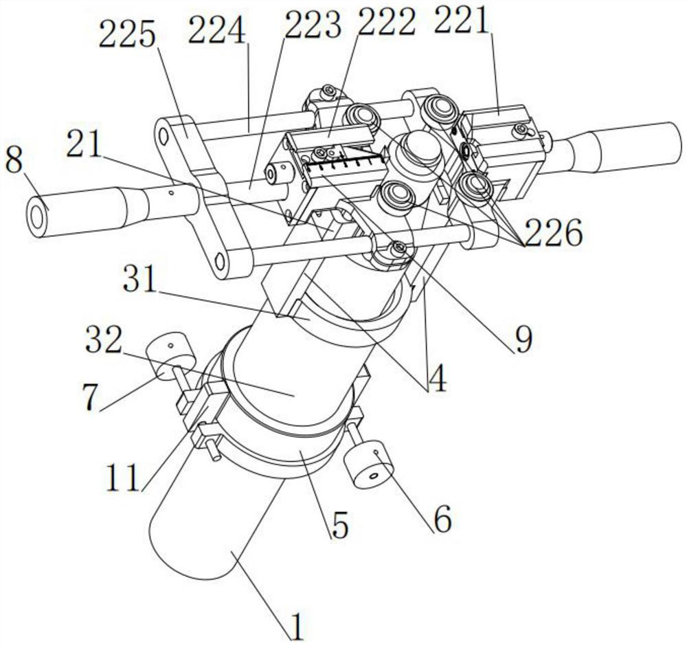
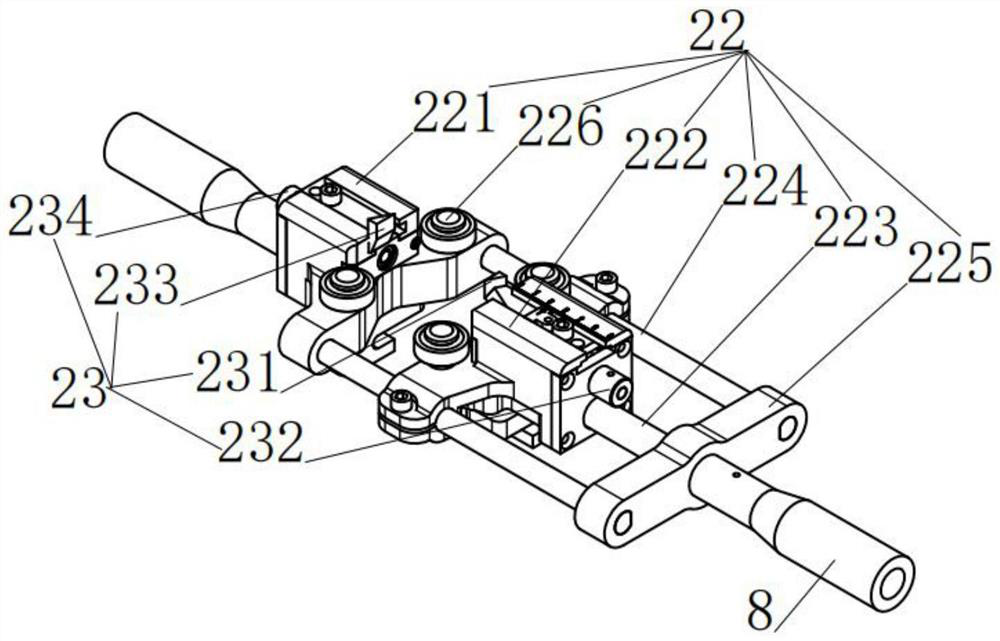
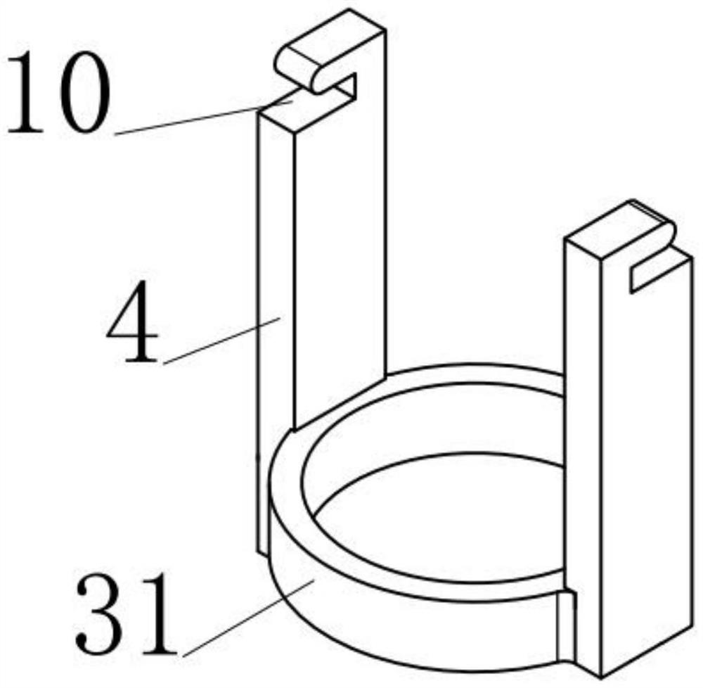

Image

  • Stripping and cutting device capable of accurately controlling stripping and cutting depth of cable insulation layer
  • Stripping and cutting device capable of accurately controlling stripping and cutting depth of cable insulation layer
  • Stripping and cutting device capable of accurately controlling stripping and cutting depth of cable insulation layer

Examples


Embodiment Construction

[0028] In order to make the objectives, technical solutions and advantages of the present invention more clearly understood, the present invention will be described in further detail below with reference to the accompanying drawings and embodiments. It should be understood that the specific embodiments described herein are only used to explain the present invention, not for The invention is limited.

[0029] In the description of the present invention, it should be noted that the terms "center", "upper", "lower", "left", "right", "vertical", "horizontal", "inner", "outer", etc. The indicated orientation or positional relationship is based on the orientation or positional relationship shown in the accompanying drawings, and is only for the convenience of describing the present invention and simplifying the description, rather than indicating or implying that the indicated device or element must have a specific orientation or a specific orientation. construction and operation, a...


PUM


Abstract

The invention relates to the technical field of power cable installation construction and power cable operation and maintenance tools, and discloses a stripping and cutting device capable of accurately controlling the stripping and cutting depth of a cable insulation layer, the stripping and cutting device comprises a stripping and cutting mechanism used for stripping and cutting a cable, and one side of the stripping and cutting mechanism is provided with a radial depth control mechanism matched with the stripping and cutting mechanism. The stripping and cutting mechanism comprises a nut connecting seat, a nut connecting rod is movably connected to the nut connecting seat, the radial depth control mechanism comprises an inner threaded sleeve and an outer threaded sleeve, the end, away from the nut connecting seat, of the nut connecting rod is in bolted connection with the inner threaded sleeve, the inner threaded sleeve is in threaded connection with the outer threaded sleeve, and the outer threaded sleeve is in threaded connection with the nut connecting seat. The end, away from the inner thread sleeve, of the outer thread sleeve is sleeved with an outer thread sleeve fixing base, the outer thread sleeve fixing base is provided with a forward adjusting screw and a reverse adjusting screw, and the manufacturing and machining quality of the cable connector in actual work is improved.

Description

technical field [0001] The invention relates to the technical field of power cable installation and construction and power cable operation and maintenance tools, in particular to a stripping and cutting device that can precisely control the depth of stripping and cutting the insulation layer of the cable. Background technique [0002] XLPE insulated power cables are mainly used to transmit electrical energy in the distribution network of power systems, including power cables with various voltage levels of 1-500kV and above and various insulations. [0003] The structure of XLPE insulated power cables with voltage levels of 110kV and above is cylindrical and formed by 9 layers of various materials. Stripping and cutting the insulation layer is the most critical link in the production of cable connectors. Its quality is related to the service life of the cable, as well as the quality, efficiency and cost of construction and maintenance. Once there is a problem in the productio...

Claims


Application Information

Patent Timeline
Patent Type & Authority Applications(China)
IPC IPC(8): H02G1/14H02G1/12
CPCH02G1/14H02G1/1224Y02W30/82
Inventor 何鹏唐静杨文望潘能键袁维益陆正继何由之
Owner 广西新南润电力科技有限公司
Learn More