
Novel electromechanical cleaning device

A cleaning device, electromechanical technology, applied in the directions of cleaning methods and utensils, cleaning methods using liquids, cleaning methods using tools, etc., can solve problems such as increasing the workload of staff, increasing cleaning costs, and inability to recycle, and reduce The effect of manual assistance, reducing cleaning costs, and reducing waste

Pending Publication Date: 2020-07-10
HENAN POLYTECHNIC INST
View PDF9 Cites 3 Cited by
  • Summary
  • Abstract
  • Description
  • Claims
  • Application Information

AI Technical Summary

Problems solved by technology

[0002] In the process of mechanical production and processing, it is often necessary to clean various mechanical parts or mechanical equipment, so cleaning devices are used accordingly, and cleaning equipment can be used to replace manual cleaning of workpiece surface oil, wax, dust, Mechanical equipment for stains and stains such as oxide layers; cleaning equipment seen on the market are: ultrasonic cleaning, high-pressure spray cleaning, laser cleaning, steam cleaning, dry ice cleaning and composite cleaning equipment, etc.; among them, the most widely used current It belongs to spray cleaning and ultrasonic cleaning; in the process of industrial production and electronic product production, with the improvement of the surface cleanliness of product parts, ultrasonic precision cleaning methods are being paid more and more attention and recognized by people, but the existing Due to the limitation of the structure of the electromechanical cleaning device, the cleaning parts and cleaning nozzles are fixed, so that only part of the parts surface can be cleaned, so the cleaning parts need to be rotated many times, which increases the workload of the staff and reduces the In addition, when using water, it generally cannot be recycled, which leads to the waste of water resources and increases the cost of cleaning

Method used


Image

  • Novel electromechanical cleaning device
  • Novel electromechanical cleaning device
  • Novel electromechanical cleaning device

Examples


Embodiment Construction

[0018] The following will clearly and completely describe the technical solutions in the embodiments of the present invention with reference to the accompanying drawings in the embodiments of the present invention. Obviously, the described embodiments are only some, not all, embodiments of the present invention. Based on the embodiments of the present invention, all other embodiments obtained by persons of ordinary skill in the art without making creative efforts belong to the protection scope of the present invention.

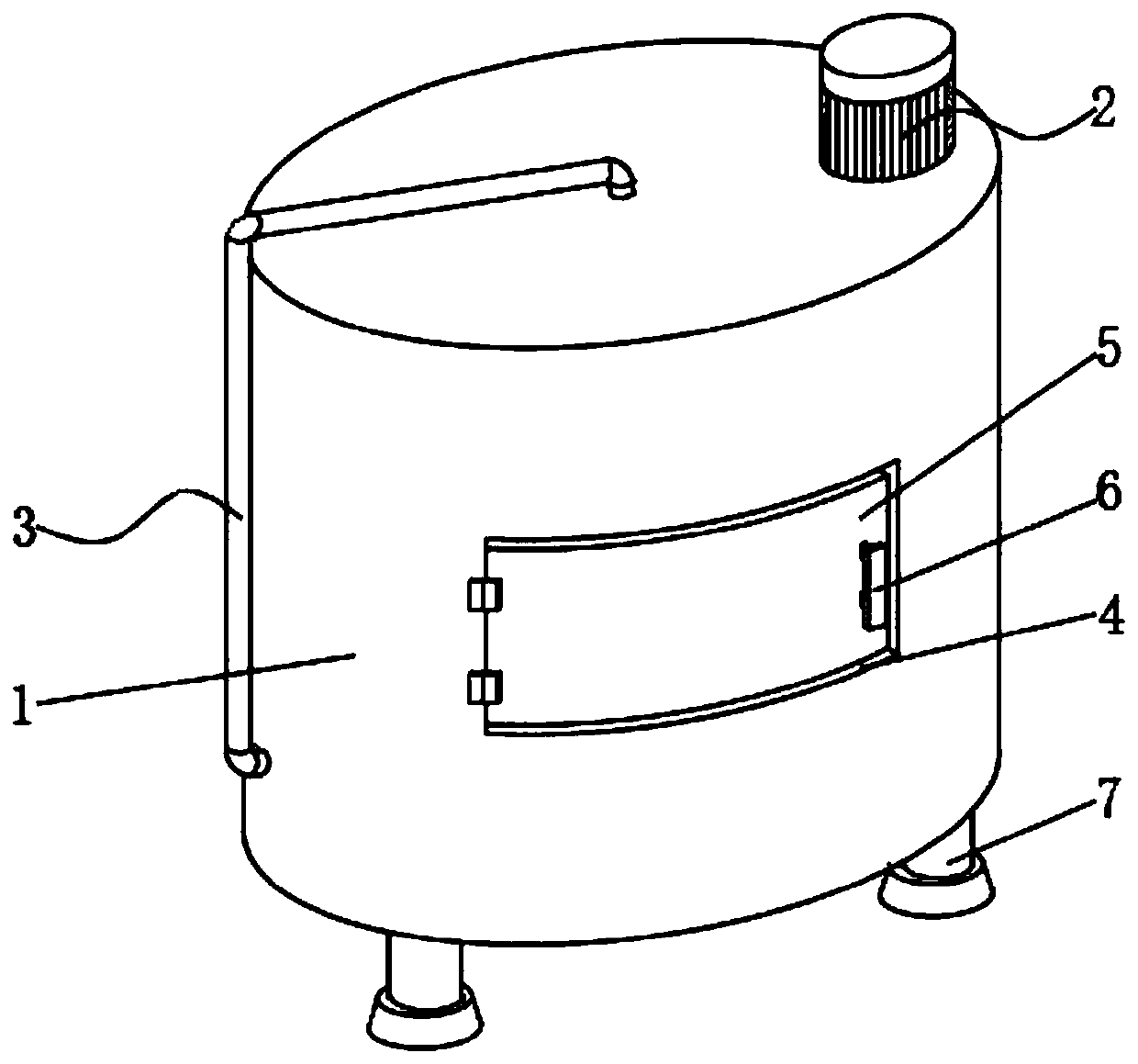
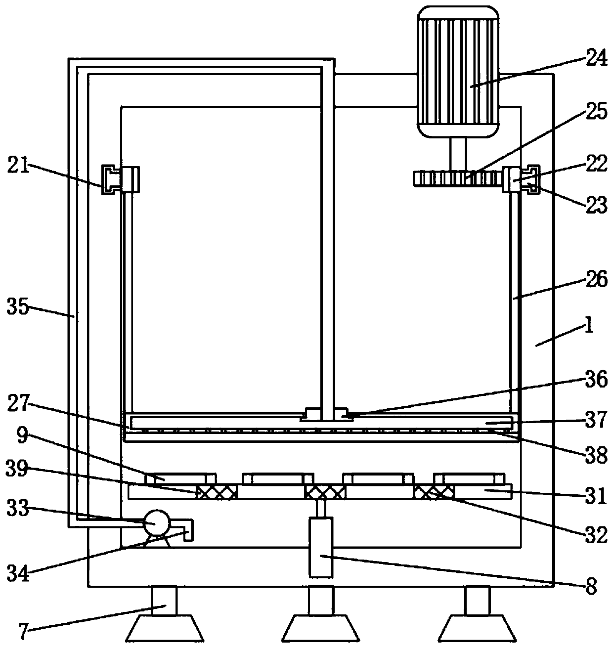
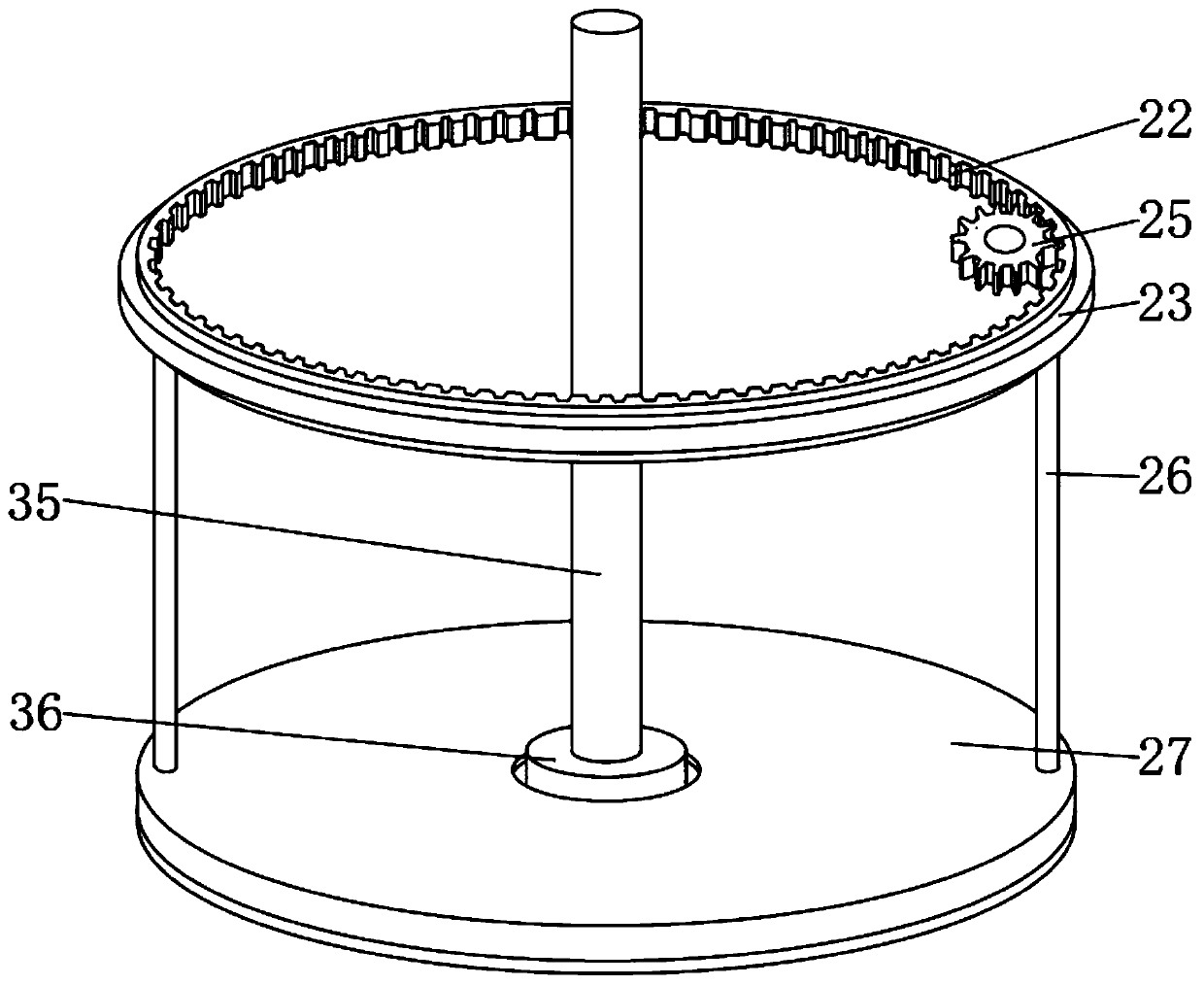
[0019] see Figure 1-3 , the present invention provides a technical solution: a new electromechanical cleaning device, including a cleaning tank main body 1, a cleaning component 2, a water component 3, a discharge port 4, a baffle plate 5, a handle 6, a support 7, a hydraulic rod 8 and The ring 9 is placed, and the cleaning assembly 2 is fixed on the inner wall of one side of the cleaning tank main body 1; the cleaning assembly 2 includes a rotating groove 21...


PUM


Abstract

The invention discloses a novel electromechanical cleaning device. The device comprises a cleaning tank main body, a clearing assembly, a water using assembly, a placing opening, a baffle, a handle, asupport, a hydraulic rod and a containing ring, wherein the clearing assembly is fixed to the inner wall of one side of the cleaning tank main body; the clearing assembly comprises a rotating groove,an annular rack, a sliding block, a motor, a gear, a connecting rod and a brush disc, the annular rack is installed on the inner wall of one side of the cleaning tank main body, the gear is connectedto the outer wall of one side of the annular rack in a meshing mode, and the motor is embedded in the outer wall of the top end of the cleaning tank main body. According to the electromechanical cleaning device, the clearing device and the water using device are adopted, so that parts can be rapidly cleaned without rotating a cleaning component, manual assistance is reduced, the workload of workers is reduced, the working efficiency is improved, water resources can be recycled, waste of the water resources is reduced, the water using efficiency is improved, and the cleaning cost is reduced.

Description

technical field [0001] The invention relates to the technical field of electromechanical cleaning equipment, in particular to a novel electromechanical cleaning device. Background technique [0002] In the process of mechanical production and processing, it is often necessary to clean various mechanical parts or mechanical equipment, so cleaning devices are used accordingly, and cleaning equipment can be used to replace manual cleaning of workpiece surface oil, wax, dust, Mechanical equipment for stains and stains such as oxide layers; cleaning equipment seen on the market are: ultrasonic cleaning, high-pressure spray cleaning, laser cleaning, steam cleaning, dry ice cleaning and composite cleaning equipment, etc.; among them, the most widely used current It belongs to spray cleaning and ultrasonic cleaning; in the process of industrial production and electronic product production, with the improvement of the surface cleanliness of product parts, ultrasonic precision cleanin...

Claims


Application Information

Patent Timeline
Patent Type & Authority Applications(China)
IPC IPC(8): B08B1/04B08B3/04B08B3/14
CPCB08B3/04B08B3/14B08B1/32
Inventor 席东河焦欣欣杨云杨旭靳果张振晗
Owner HENAN POLYTECHNIC INST
Learn More