A voltage equalization control method and system for a rail transit supercapacitor energy storage system

A technology of super capacitor and energy storage system, applied in control/regulation system, current collector, electric vehicle, etc., can solve the problems of unbalanced pressure, low utilization rate of regenerative braking energy, low utilization rate of super capacitor, etc. Efficient use effect

Active Publication Date: 2022-05-03
南京国电南自新能源科技有限公司
View PDF5 Cites 0 Cited by
  • Summary
  • Abstract
  • Description
  • Claims
  • Application Information

AI Technical Summary

Problems solved by technology

In the prior art, the supercapacitor energy storage system with independent input in series and output has problems such as unbalanced pressure in the process of regenerative braking energy absorption and release, low utilization rate of supercapacitors, and low utilization rate of regenerative braking energy.

Method used


Image

  • A voltage equalization control method and system for a rail transit supercapacitor energy storage system
  • A voltage equalization control method and system for a rail transit supercapacitor energy storage system
  • A voltage equalization control method and system for a rail transit supercapacitor energy storage system

Examples


Embodiment 1

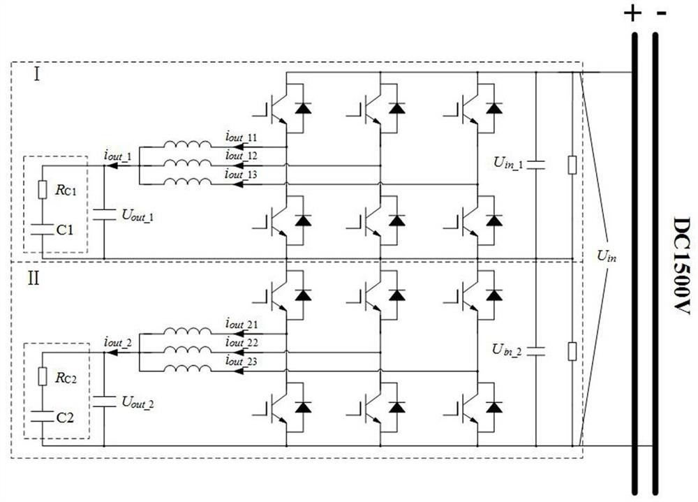
[0028] based on figure 1 The shown rail transit supercapacitor energy storage system includes two sets of input in series and independent outputs. This embodiment provides a voltage equalization control method for a rail transit supercapacitor energy storage system, including:

[0029] Collect the output voltages on the output side of converter Ⅰ and converter Ⅱ respectively U out_1 and U out_2 ,Will U out_1 and U out_2 Make a difference, get the pressure equalization distribution adjustment coefficient through PI controller adjustment and limit processing, and then superimpose with the default pressure equalization coefficient 0.5 as the input side pressure equalization proportional coefficient k vot_Equal ;

[0030] Collect the input voltage of the input side of converter Ⅰ and converter Ⅱ separately U in_1 and U in_2 ,Will U in_1 and U in_2 After summation and input side pressure proportional coefficient k vot_EqualMultiplied, and then with the input volt...

Embodiment 2

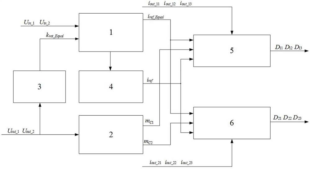
[0036] A rail transit supercapacitor energy storage system voltage equalization control system, such as figure 1 , figure 2 As shown, it includes the input series side voltage equalization controller 1, the output side super capacitor voltage equalization controller 3, the total voltage controller 4, the converter I current controller 5, the converter II current controller 6, and the super capacitor anti-overcharge Or the over-discharge regulator controller 2, the output side supercapacitor voltage equalizer controller 3 collects the output voltage of the output side of the converter Ⅰ and converter Ⅱ U out_1 and U out_2 , and output the proportional coefficient of the input side pressure equalization k vot_Equal ;Input series side voltage equalization controller 1 collects the input voltage of the input side of converter Ⅰ and converter Ⅱ U in_1 and U in_2 Combined with the input side pressure equalization proportional coefficient k vot_Equal , output current devi...


PUM


Abstract

The invention discloses a rail transit supercapacitor energy storage system voltage equalization control method and system in the technical field of rail transit regenerative electric braking. Converter, multiple converter current controllers, supercapacitor anti-overcharge or over-discharge regulator controllers, respectively collect the output voltage on the output side of each converter, the input voltage on the input side, and the current of each branch of each converter, according to Calculate the current given adjustment coefficient of each converter from the maximum charging voltage value or minimum discharge voltage value allowed by the supercapacitor in different working modes and the start-up hysteresis threshold; obtain the duty cycle of each branch of each converter; and then realize the output The voltage equalization control of the side supercapacitor and the maximum utilization of the capacitor charge, while ensuring that the two sets of converters connected in series on the input side work in a controllable safe voltage range, efficiently utilize the energy generated by rail transit regenerative braking.

Description

technical field [0001] The invention belongs to the technical field of rail transit regenerative electric braking, and in particular relates to a voltage equalization control method and system for a rail transit supercapacitor energy storage system. Background technique [0002] The distance between urban rail transit stations is short and the number of stations is large, so trains start and brake frequently. At present, regenerative electric braking is generally used for vehicles. During regenerative electric braking, the traction motor runs in the power generation mode and feeds regenerative energy to the traction network. If this part of energy cannot be consumed by other vehicles on the line, the bus voltage will rise. In order to control the safety of equipment, the current regenerative braking schemes are mainly divided into three types: dissipation type, energy feedback type and energy storage type. The dissipative type mainly converts the braking energy into heat en...

Claims


Application Information

Patent Timeline
Patent Type & Authority Patents(China)
IPC IPC(8): H02J7/00H02M3/158
CPCH02J7/0068H02J7/0013H02M3/158H02M3/1584H02J7/345
Inventor 杨轶成王响成郭伟刘春松李冰
Owner 南京国电南自新能源科技有限公司
Why Eureka
Try Eureka