
Heating furnace assembly of high-temperature friction-wear experimental instrument and using method of heating furnace assembly

A technology of friction and wear and heating furnace, which is applied in the direction of instruments, scientific instruments, and testing wear resistance, etc. It can solve the problems of not being too long for a single test, reducing the service life of equipment, and affecting heating performance.

Pending Publication Date: 2020-07-07
兰州华汇仪器科技有限公司
View PDF11 Cites 0 Cited by
  • Summary
  • Abstract
  • Description
  • Claims
  • Application Information

AI Technical Summary

Problems solved by technology

[0004] First, although cooling chamber 1 and cooling chamber 2 filled with coolant are installed to cool the shaft, this cooling method is only effective for a short period of time. If the experiment takes a long time, the coolant will inevitably be The temperature of the process continues to rise, and there is no other effective heat dissipation method to solve this problem at this time, which will lead to the failure or deterioration of the coolant, which will further cause the shaft and the limit plate to be deformed and bent by heat, thereby reducing the service life of the equipment. Therefore, the There are major technical defects in the improvement of this method
[0005] The second is that if you want to improve the life of the equipment according to the above problems, when you need to use the equipment, the single test time should not be too long, and if you need to conduct the next test, you can only wait for the equipment to cool down to a suitable temperature. low work efficiency
[0006] Third, in the high-temperature friction and wear experiment, the test piece should be completely exposed to the heating chamber of the heating furnace, so as to ensure that the test piece can be fully and accurately heated. The tray is set outside the heating furnace, which cannot guarantee whether the heating of the test piece is comprehensive and accurate. At the same time, no other detection means are set to determine the actual temperature of the test piece, so the influence of temperature on the surface properties of the material cannot be accurately projected, and the final result is Experimental data is also inaccurate
[0007] The fourth is that there is no heat insulation and heat preservation device. On the one hand, the heating furnace is completely exposed to the outside, so that heat can be continuously lost from around the heating furnace, which affects the heating performance; They are all in a high temperature state, which seriously affects the safe use of the equipment, reduces the service life of the equipment, and is easy to cause personal injury

Method used


Image

  • Heating furnace assembly of high-temperature friction-wear experimental instrument and using method of heating furnace assembly
  • Heating furnace assembly of high-temperature friction-wear experimental instrument and using method of heating furnace assembly
  • Heating furnace assembly of high-temperature friction-wear experimental instrument and using method of heating furnace assembly

Examples


Embodiment 1

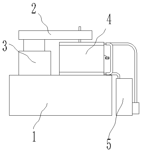
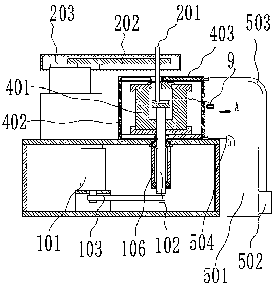
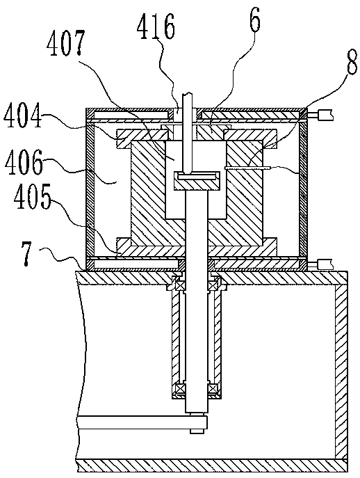
[0040] Embodiment one, such as Figure 1-3As shown, a heating furnace assembly of a high-temperature friction and wear tester includes a machine base 1, a dynamometer head 2, a machine head support 3 and a heating furnace assembly 4, and the machine head support 3 and the heating furnace assembly 4 are fixedly connected to the machine base 1 Above, the dynamometer head 2 is connected to the head support 3, the dynamometer head 2 is arranged above the head support 3 and the heating furnace assembly 4, and the dynamometer head 2 includes a loading bar 201, a beam 202 and a force Value sensor 203, the loading rod 201 is connected on the beam 202, the force sensor 203 is connected between the beam 202 and the head support 3, the loading rod 201 is inserted into the heating furnace assembly 4, and the motor 101 is arranged in the base 1 , a rotating shaft 102, a gear toothed belt 103, a friction disc 104 and a detection piece 105, the rotating shaft 102 is rotatably connected in th...

Embodiment 2

[0046] Embodiment two, such as Figure 4 As shown, a bearing housing 106 is further provided in the machine base 1, the bearing housing 106 is fixedly connected to the upper part of the machine base 1, and the rotating shaft 102 is rotatably connected in the bearing housing 106 through a bearing, and the return pipe 504 runs through the machine base 1. The return water pipe 504 is spirally wound outside the bearing housing 106 in the machine base 1, and the rotating shaft 102 is fixed and supported through the bearing housing 106, and the heat is transferred to the bearing housing 106 through the bearing, and then the heat is dissipated through the return water pipe 504.

[0047] Further, the thermal insulation cavity 406 is filled with thermal insulation materials, which can effectively insulate heat, reduce heat transfer to the outside on the one hand, and ensure the temperature maintenance effect of the heating cavity 407 on the other hand. The thermal insulation materials c...


PUM


Abstract

The invention relates to a high-temperature friction-wear experimental instrument, and particularly relates to a heating furnace assembly of a high-temperature friction-wear experimental instrument and a using method of the heating furnace assembly. The heating furnace assembly of the high-temperature friction-wear experimental instrument comprises a machine base, a force measuring machine head, amachine head support and a heating furnace assembly, wherein the machine head support and the heating furnace assembly are fixedly connected to the upper part of the machine base, the force measuringmachine head is connected to the machine head support, the force measuring machine head is arranged above the machine head support and the heating furnace assembly, the force measuring machine head comprises a loading rod, a cross beam and a force value sensor, the loading rod is connected to the cross beam, the force value sensor is connected between the cross beam and the machine head support,the loading rod is inserted into the heating furnace assembly, the machine base is internally provided with a motor, a rotating shaft, a gear toothed belt, a friction disc and a detection piece, the rotating shaft is rotatably connected in the machine base and vertically arranged, the rotating shaft penetrates through the machine base, the friction disc and is fixedly connected to the upper end ofthe rotating shaft, the friction disc is arranged in the heating furnace assembly, the detection piece is clamped between the friction disc and the loading rod, and the motor drives the rotating shaft to rotate through the gear toothed belt.

Description

technical field [0001] The invention relates to a high-temperature friction and wear tester, in particular to a heating furnace assembly of a high-temperature friction and wear tester and a method for using the same. Background technique [0002] The high-temperature friction and wear tester is an instrument and equipment used for material surface performance testing. It is widely used in the field of material science and technology. Chinese patent 201310311447.6 discloses a high-temperature friction and wear tester. The tester also includes a The bushing, the bushing includes a body and a limit plate located at the upper end of the body, the lower end surface of the limit plate is fixedly connected with the upper surface of the table, when the cylinder shrinks, the limit plate Can be attached to the bottom of the high-temperature furnace, the limiting plate is provided with a cooling chamber 1 filled with cooling liquid, and the body is provided with a cooling chamber 2 fil...

Claims


Application Information

Patent Timeline
IPC IPC(8): G01N3/56G01N3/02
CPCG01N3/56G01N3/02G01N2203/0676G01N2203/0226G01N2203/0228
Inventor 华敏奇张国珍
Owner 兰州华汇仪器科技有限公司
Learn More