Fixing protecting device for hydraulic oil tanks of engineering machinery

A hydraulic oil tank, fixed protection technology, applied in the direction of oil supply oil tank device, fluid pressure actuating device, mechanical equipment, etc., can solve the problems of shortening the service life of construction machinery, increasing maintenance cost of construction machinery, damage, etc.

Inactive Publication Date: 2020-07-07
刘京標
View PDF1 Cites 0 Cited by
  • Summary
  • Abstract
  • Description
  • Claims
  • Application Information

AI Technical Summary

Problems solved by technology

[0006] The purpose of the present invention is to provide a fixed protection device for the hydraulic oil tank of engineering machinery, to solve the problem proposed in the background technology, although the heat dissipation area of ​​the hydraulic oil tank can be increased by adding heat dissipation fins to speed up the heat transfer of the hydraulic oil tank to the outside world. The speed of the air helps to reduce the temperature of the hydraulic oil to increase the life of the hydraulic components, but the heat dissipation effect is poor, especially in the hot summer, it may become the source of heat conduction, and there is no shock-absorbing protection measure, which is easy to be caused by the vibration of construction machinery And cause damage to the hydraulic oil tank, resulting in abnormal operation of the construction machinery, shortening the service life of the construction machinery, and increasing the maintenance cost of the construction machinery

Method used


Image

  • Fixing protecting device for hydraulic oil tanks of engineering machinery
  • Fixing protecting device for hydraulic oil tanks of engineering machinery
  • Fixing protecting device for hydraulic oil tanks of engineering machinery

Examples


Embodiment Construction

[0022] The following will clearly and completely describe the technical solutions in the embodiments of the present invention with reference to the accompanying drawings in the embodiments of the present invention. Obviously, the described embodiments are only some, not all, embodiments of the present invention. Based on the embodiments of the present invention, all other embodiments obtained by persons of ordinary skill in the art without creative efforts fall within the protection scope of the present invention.

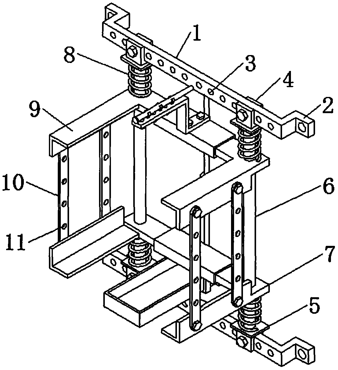
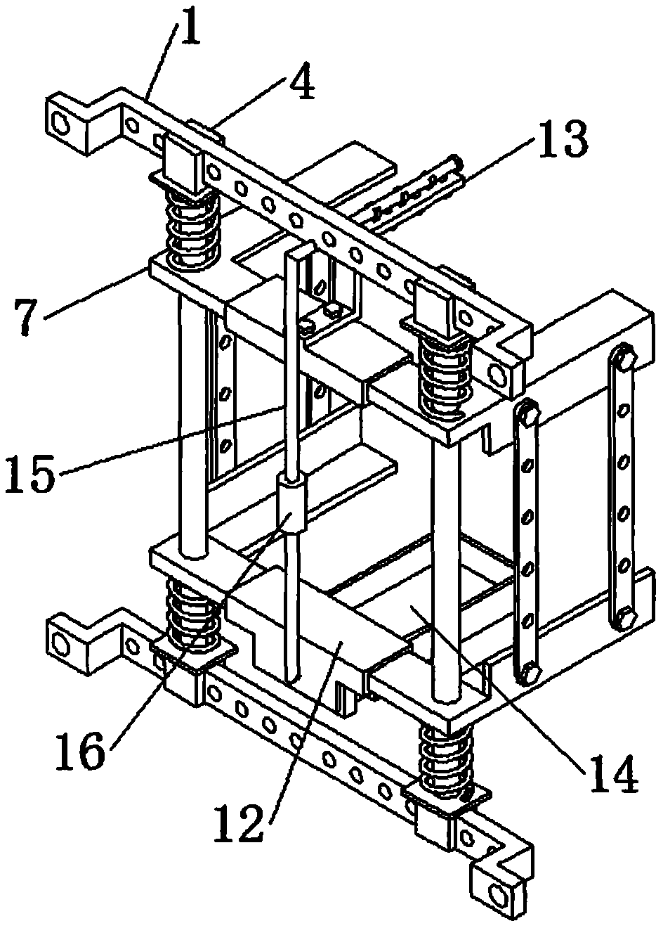
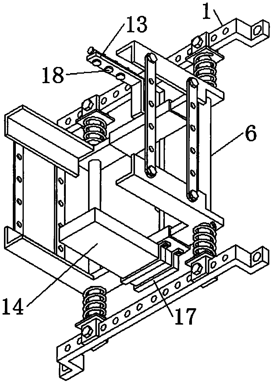
[0023] see Figure 1-5 , the present invention provides a technical solution: a fixed protection device for engineering machinery hydraulic oil tanks, including two sets of positioning support plates 1, and the two sets of positioning support plates 1 are arranged in parallel up and down, and the left and right ends of the positioning support plates 1 are An L-shaped connecting plate 2 is provided, and positioning screw holes 3 are evenly opened on the outer wall o...


PUM


Abstract

The invention discloses a fixing protecting device for hydraulic oil tanks of engineering machinery, and beings to the technical field of engineering machinery. The device comprises two positioning supporting plates, the two positioning supporting plates are arranged in parallel up and down, L-shaped connecting plates are arranged at the left ends and the right ends of the positioning supporting plates, and positioning screw holes are uniformly formed in the outer walls of the positioning supporting plates. According to the device, the hydraulic oil tanks are arranged among four right-angle supporting plates, by adjusting the positions of fastening screws in adjusting screw holes and adjusting the positions of the fastening screws in positioning screw holes, stabilizing connecting plates can be subjected to fixed-height adjusting, positioning clamping blocks can be subjected to fixed-width adjusting, so that through the device, the hydraulic oil tanks of different models can be arranged and fixed, the application range is widened, due to the elastic effect of buffering elastic pieces, the heat transmission of the engineering machinery to the hydraulic oil tanks fixed among the right-angle supporting plates is reduced, and the damage to the hydraulic oil tanks caused by vibration of the engineering machinery is reduced.

Description

technical field [0001] The invention relates to the technical field of construction machinery, in particular to a fixed protection device for hydraulic oil tanks of construction machinery. Background technique [0002] Construction machinery is an important part of the equipment industry. In a nutshell, the mechanical equipment necessary for comprehensive mechanized construction projects required for earthwork construction projects, road surface construction and maintenance, mobile lifting and unloading operations, and various construction projects is called construction machinery. At present, construction machinery generally uses hydraulic pressure. Power, and the hydraulic oil tank is an important part of the hydraulic system. Most of the oil tank is closer to the engine compartment. Due to the high temperature of the air outlet, the heat in the air is easily transferred to the hydraulic oil tank, resulting in an additional heat load for the hydraulic oil tank. The hydrau...

Claims


Application Information

Patent Timeline
IPC IPC(8): F15B1/26F15B21/0423F16F15/04
CPCF15B1/26F15B21/008F15B21/042F15B2211/62
Inventor 刘京標
Owner 刘京標
Why Eureka
Try Eureka