
Device and method for continuously removing suspended matters in crude oil

A suspension and removal technology, applied in the field of petrochemical industry, can solve problems such as incomplete removal, affecting desalination effect, easy to block devices, etc.

Active Publication Date: 2020-07-07
CHINA PETROLEUM & CHEM CORP +1
View PDF5 Cites 0 Cited by
  • Summary
  • Abstract
  • Description
  • Claims
  • Application Information

AI Technical Summary

Problems solved by technology

[0007] In view of the lack of equipment in the prior art that can effectively remove suspended solids in oil products, the device is easily blocked during the removal process, and the removal is not complete, which greatly affects the subsequent desalination effect. The present invention provides a continuous removal The device and method for suspended solids in crude oil have a good effect of removing suspended solids and high treatment efficiency

Method used


Image

  • Device and method for continuously removing suspended matters in crude oil
  • Device and method for continuously removing suspended matters in crude oil

Examples


Embodiment 1

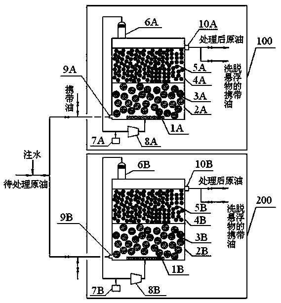
[0035] A device for continuously removing suspended solids in crude oil, such as figure 1 As shown, the air flotation removal system Ⅰ100 and the air flotation removal system Ⅱ200 are included. The air flotation removal system Ⅰ100 includes a first-level air-flotation removal section 2A and a second-level air-flotation removal section 4A arranged sequentially from bottom to top. The first-level air flotation removal section 2A is filled with a first-level air-floating packing layer 3A, the packing is macroporous honeycomb packing, and the density is 550kg / m 3 , The porosity is 65%~70%; the secondary air flotation removal section 4A is filled with the secondary air flotation packing layer 5A, the packing is macroporous honeycomb packing, and the density is 570kg / m 3 , The porosity is 25%-30%; the above-mentioned fillers are all polypropylene fillers; the bottom of the first-stage air flotation removal section 2A is provided with a micro-bubble generator 1A, and the inlet of the mi...

Embodiment 2

[0039] A device for continuously removing suspended solids in crude oil, except that the porosity of the first-stage air-floating packing layers 3A and 3B is 75% to 80%, and the porosity of the second-stage air-floating packing layers 5A and 5B is 30% to 35%. Other structure and arrangement are the same as in Example 1.

Embodiment 3

[0041] The device for removing suspended solids in oil, except for the first-level air-floating packing layers 3A and 3B, which are filled with macroporous wire mesh, the porosity is 65% to 70%, and the porosity of the second-level air-floating packing layers 5A and 5B are Except for 20% to 25%, other structures and settings are the same as in Example 1.


PUM

PropertyMeasurementUnit
Densityaaaaaaaaaa
Densityaaaaaaaaaa
Porosityaaaaaaaaaa

Abstract

The invention discloses a device and a method for continuously removing suspended matters in crude oil. The device comprises two sets of air floatation removal systems, each set comprising at least two stages of air floatation removal sections which are sequentially arranged from bottom to top; the porosity of the filler in the upper-layer air floatation removal section is always smaller than thatof the filler in the lower-layer air floatation removal section, and a microbubble generator is arranged at the bottom of the first-stage air floatation removal section; when suspended solids in crude oil are removed, low-gas-amount gas inflow is adopted, and when the suspended solids in the filler are desorbed, high-gas-amount gas inflow is adopted. While suspended solids in raw materials are effectively removed, cleaning purification and suspended solid desorption of the filler are achieved on line, so that the problem that the adsorption efficiency of the filler is reduced and even the filler is blocked by the suspended solids along with increase of the suspended solids on the surface can be solved, and long-period efficient operation of the device is guaranteed.

Description

Technical field [0001] The invention belongs to the technical field of petrochemical industry, and is specifically a device for continuously removing suspended solids in crude oil and a method for removing suspended solids by using it. Background technique [0002] Crude oil contains water and salts such as sodium chloride, calcium chloride and magnesium chloride. In order not to affect crude oil processing, the first step of crude oil processing is desalination and dehydration, so that the water content is 0.1% to 0.2%, and the salt content <5mg / L, and for refineries with residual oil hydrogenation or heavy oil cracking, the requirements are more stringent. The salt content in the raw oil is required to be <3mg / L. With the increasing trend of crude oil deterioration and heavy oil quality, Many crude oils contain a certain amount of colloidal suspended matter, which brings more problems to the crude oil dehydration and desalination process and subsequent processing equipmen...

Claims


Application Information

Patent Timeline
IPC IPC(8): C10G53/02
CPCC10G53/02
Inventor 阮宗琳杨秀娜何佳李经伟金平
Owner CHINA PETROLEUM & CHEM CORP
Learn More