Method for laser turn-milling compound machining of tool
A composite processing and laser processing technology, which is applied in the direction of manufacturing tools, laser welding equipment, metal processing equipment, etc., can solve the problems of increasing processing costs, affecting processing efficiency and processing accuracy, etc.
- Summary
- Abstract
- Description
- Claims
- Application Information
AI Technical Summary
Problems solved by technology
Method used
Image

Examples
Embodiment 1
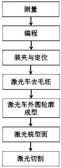
[0035] A method for laser turning and milling compound processing tool, comprising the following steps:
[0036] S1. Measurement: measure the shape and size of the tool bar to be processed;
[0037] S2. Programming: Write the laser processing path and process program according to the measurement results of the tool bar to be processed and the final tool shape and accuracy requirements;
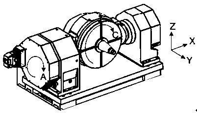
[0038] S3. Clamping: Clamp the tool bar to the central turntable of the laser machine tool, and use the probe to position the tool;
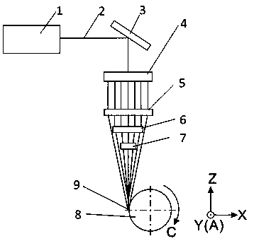
[0039] S4. Laser turning to remove the blank: the laser turning method is used to remove the blank on the outer surface of the tool to be processed, and obtain a tool bar with a prefabricated outer diameter;
[0040] S5. Laser turning outer circle contour forming: the outer surface of the tool is processed by laser turning to obtain the prefabricated contour shape and size, the surface roughness is Ra1μm, and the processing accuracy is 20μm;
[0041] S6. Laser...
Embodiment 2
[0055] A method for laser turning and milling compound processing tool, comprising the following steps:
[0056] S1. Measurement: measure the shape and size of the tool bar to be processed;
[0057] S2. Programming: Write the laser processing path and process program according to the measurement results of the tool bar to be processed and the final tool shape and accuracy requirements;
[0058] S3. Clamping: Clamp the tool bar to the central turntable of the laser machine tool, and use the probe to position the tool;
[0059] S4. Laser turning to remove the blank: the laser turning method is used to remove the blank on the outer surface of the tool to be processed, and obtain a tool bar with a prefabricated outer diameter;
[0060] S5. Laser turning outer circle contour forming: According to the shape and size of the prefabricated contour, there is no need to use laser turning to process the outer surface of the tool;
[0061] S6. Laser milling surface: the tool is processed...
Embodiment 3
[0074] A method for laser turning and milling compound processing tool, comprising the following steps:
[0075] S1. Measurement: measure the shape and size of the tool bar to be processed;
[0076] S2. Programming: Write the laser processing path and process program according to the measurement results of the tool bar to be processed and the final tool shape and accuracy requirements;
[0077] S3. Clamping: Clamp the tool bar to the central turntable of the laser machine tool, and use the probe to position the tool;
[0078] S4. Laser turning to remove the blank: the laser turning method is used to remove the blank on the outer surface of the tool to be processed, and obtain a tool bar with a prefabricated outer diameter;
[0079] S5. Laser turning outer circle contour forming: the outer surface of the tool is processed by laser turning to obtain the prefabricated contour shape and size, the surface roughness is Ra1μm, and the processing accuracy is 15μm;
[0080] S6. Laser...
PUM
| Property | Measurement | Unit |
|---|---|---|
| Surface roughness | aaaaa | aaaaa |
| Angle | aaaaa | aaaaa |
| Roughness | aaaaa | aaaaa |
Abstract
Description
Claims
Application Information
 - R&D
- Intellectual Property
- Life Sciences
- Materials
- Tech Scout
- Unparalleled Data Quality
- Higher Quality Content
- 60% Fewer Hallucinations
Browse by: Latest US Patents, China's latest patents, Technical Efficacy Thesaurus, Application Domain, Technology Topic, Popular Technical Reports.
© 2025 PatSnap. All rights reserved.Legal|Privacy policy|Modern Slavery Act Transparency Statement|Sitemap|About US| Contact US: help@patsnap.com