Electrical cabinet suitable for outdoor use

A technology for electrical cabinets and cabinets, which is applied in the field of electric power and can solve problems affecting the use of electrical cabinets

Inactive Publication Date: 2020-07-03
王婵
View PDF6 Cites 1 Cited by
  • Summary
  • Abstract
  • Description
  • Claims
  • Application Information

AI Technical Summary

Problems solved by technology

[0002] Electrical cabinets are commonly used facilities in daily electricity consumption, but most of the existing electrical cabinets are used indoors, and the environment in which they are located is relatively stable, but some electrical cabinets need to be used outdoors, such as the construction of some large projects, In this environment, the electrical cabinet will face negative factors such as exposure to the sun, rain, excessive dust or high humidity, etc. These negative factors greatly affect the use of the electrical cabinet. Therefore, a suitable outdoor use is now provided. Electrical cabinet

Method used


Image

  • Electrical cabinet suitable for outdoor use
  • Electrical cabinet suitable for outdoor use
  • Electrical cabinet suitable for outdoor use

Examples


Embodiment 1

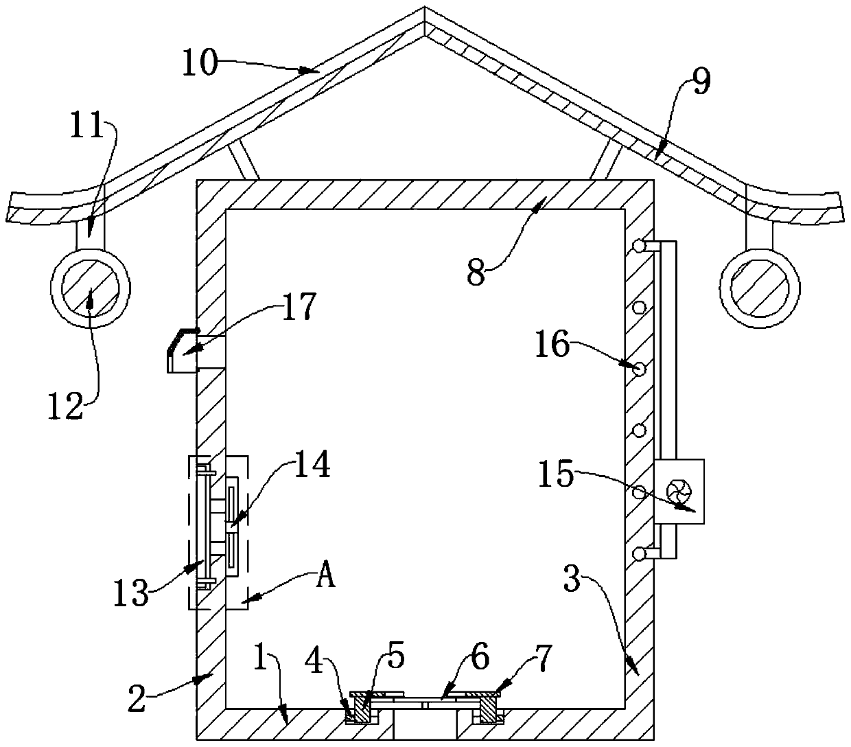
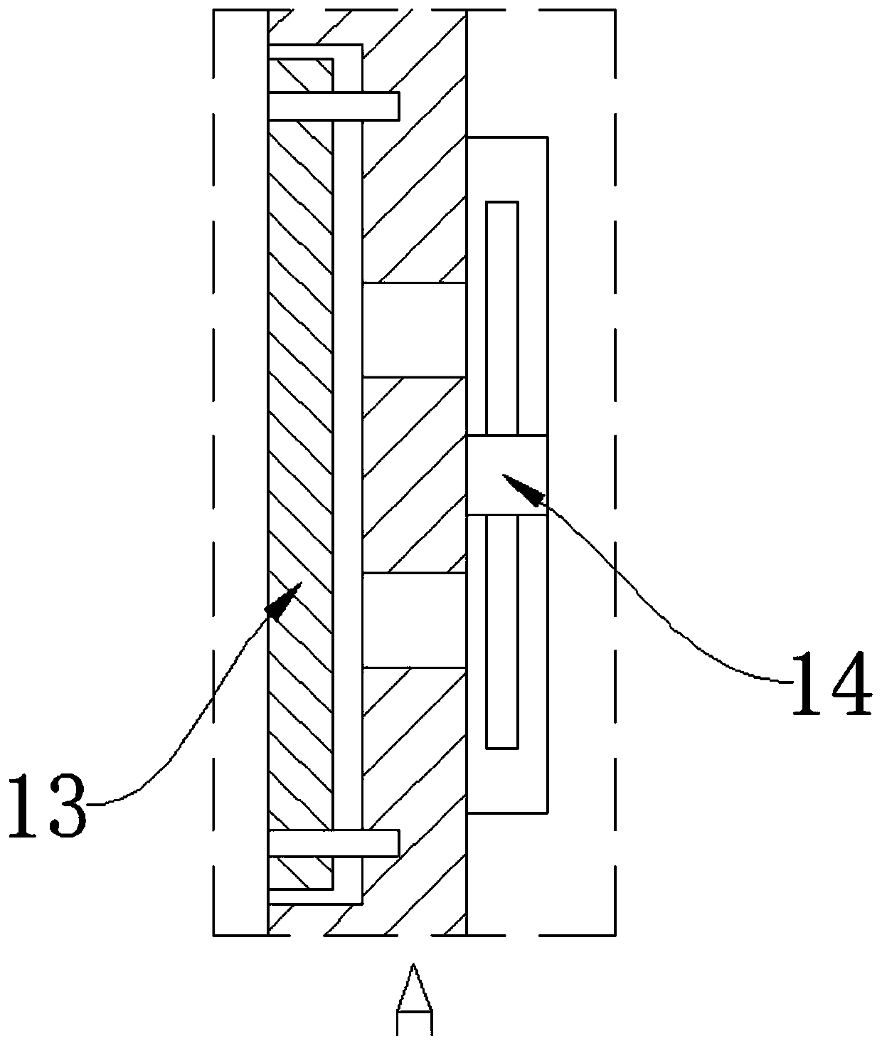
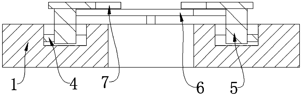
[0024] See Figure 1-7 This embodiment provides an electrical cabinet suitable for outdoor use, including a cabinet body that includes a bottom plate 1, a middle plate, and a top plate 8. The middle plate includes side panels, a front panel 2 and a rear panel 3. An upper cover plate is provided above the top plate 8, and a connecting rod for supporting is provided between the upper cover plate and the top plate 8. The upper cover plate includes a reflector plate 10 and a heat insulation plate 9. The board can play the role of sun-shading and rain-proofing. The bottom plate 1 is provided with a threading hole and a wiring structure is arranged thereon. The wiring structure includes a plurality of lower plates 6, an upper plate 7 and a clamping block 5. The bottom plate 1 A number of clamping grooves are opened on the upper part. The clamping grooves are "T"-shaped and the clamping blocks 5 are slidably arranged in the clamping grooves. The lower board 6 and the upper board 7 are...

Embodiment 2

[0032] On the basis of Example 1, a suspension rod 11 is arranged below the upper cover plate, a roller column 12 is movably arranged at the lower end of the suspension rod 11, and a thermal insulation pad is arranged on the roller column 12, so that the outdoor temperature is relatively low. When it is low, it can play a role in heat preservation and protection.

Embodiment 3

[0034] On the basis of embodiment 1, the lower end of the external plate 19 is divided into a number of movable plates 20, the external plate 19 is provided with a cylindrical shaft, the upper end of the movable plate 20 is provided with a collar and the collar is rotated and sleeved On the cylindrical shaft, such use is more convenient.


PUM


Abstract

The invention discloses an electrical cabinet suitable for outdoor use, and relates to the field of electric power and electricity. By arranging an upper cover plate, the rainproof effect can be achieved. Through the arrangement of a light reflecting plate and a heat insulation plate, exposure to the sun can be effectively prevented. The rear panel is provided with a cooling structure used for heat dissipation. The cooling structure comprises a pump body and a heat dissipation pipe. The radiating pipe is spirally arranged in the rear panel, so that the contact surface is enlarged, heat dissipation effect is improved, and overheating is prevented. An external connection hole is formed in the front panel, and an external connection structure is arranged on the outer side of the external connection hole. The edge of the external connection plate is positioned in the external connection groove. A good sealing effect can be achieved. The waterproof function can be achieved under the condition that water flow falls due to self weight while the function of an external cable is achieved, the external cable is more convenient to connect due to hinging of the external plates. A dustproof structure is further arranged on the front panel, the dustproof function can be achieved through the filtering layer, and the filtering layer is movably connected and is convenient to replace.

Description

Technical field [0001] The invention relates to the technical field of power and electricity, in particular to an electric cabinet suitable for outdoor use. Background technique [0002] Electrical cabinets are commonly used facilities in daily electricity use, but the existing electrical cabinets are mostly used indoors, and the environment in which they are located is relatively stable. However, some electrical cabinets need to be used outdoors, such as the construction of certain large-scale projects. In this environment, the electrical cabinet will face negative factors such as exposure to the sun, rain, excessive dust, or high humidity. These negative factors greatly affect the use of the electrical cabinet. Therefore, we now provide a suitable outdoor use. Electrical cabinet. Summary of the invention [0003] The object of the present invention is to provide an electrical cabinet suitable for outdoor use, so as to solve the problems raised in the background art. [0004] In ...

Claims


Application Information

Patent Timeline
Patent Type & Authority Applications(China)
IPC IPC(8): H05K5/02
CPCH05K5/0213H05K5/0217
Inventor 李涛涛王婵
Owner 王婵
Why Eureka
Try Eureka