
Head-Up Display

a display and head-up technology, applied in the field of display devices, can solve the problems of affecting image quality, damage to the components of the picture generating unit such as the screen, and damage to the optical system or picture generating unit, so as to reduce the risk of damage to other components, reduce the range of incidence angles, and improve image quality

Active Publication Date: 2020-04-02
ENVISICS LTD
View PDF1 Cites 6 Cited by
  • Summary
  • Abstract
  • Description
  • Claims
  • Application Information

AI Technical Summary

Benefits of technology

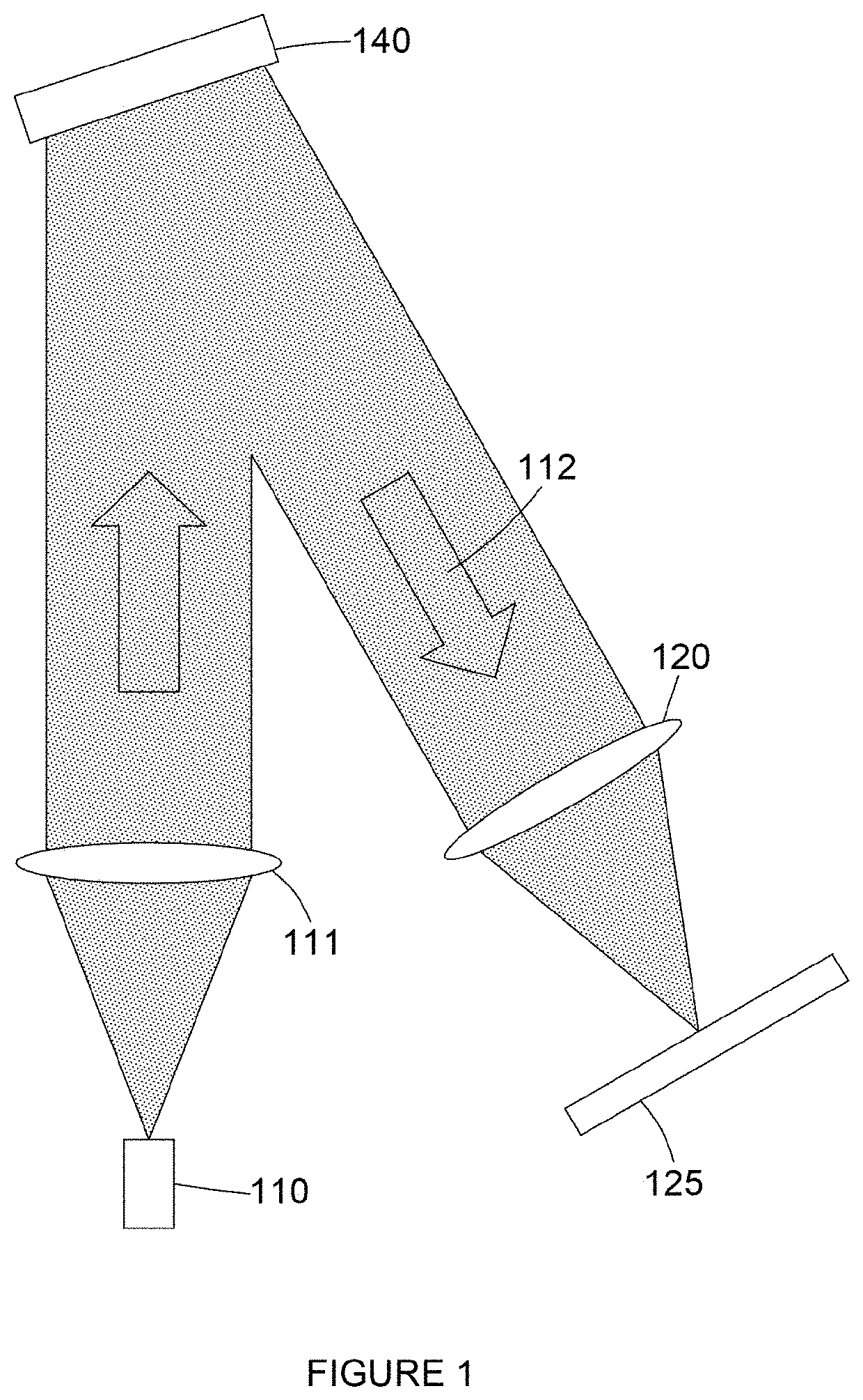
The patent describes a method for improving image quality in a head-up display by using a bandpass filter. The filter is designed to protect the picture generating unit from sunlight that may enter through the optical system. The filter has a convex surface that disperses sunlight in one direction and a concave surface that receives the light of the picture. The bandpass filter is curved in a cylindrical or conical shape to reflect sunlight off-axis. The technical effect of this configuration is that it provides better protection against sunlight without requiring the screen to be tilted. The bandpass filter is also designed to minimize the physical size of the filter and increase its de-focusing power.

Problems solved by technology

Sunlight may damage components of the optical system or picture generating unit particularly when components have optical power to magnify the picture.
Focused sunlight of sufficient power may cause damage to components of the picture generating unit such as the screen.
However, tilting the display surface off-axis is not preferable because it can negatively affect image quality and impose limitations during the design process.
The use of a bandpass filter as disclosed herein is incompatible with picture generating units having a broadband light source such as liquid crystal displays backlit by a white light source.

Method used


Image

  • Head-Up Display
  • Head-Up Display
  • Head-Up Display

Examples


Embodiment Construction

[0047]The present invention is not restricted to the embodiments described in the following but extends to the full scope of the appended claims. That is, the present invention may be embodied in different forms and should not be construed as limited to the described embodiments, which are set out for the purpose of illustration. Although different embodiments and groups of embodiments may be disclosed separately in the detailed description which follows, any feature of any embodiment or group of embodiments may be combined with any other feature or combination of features of any embodiment or group of embodiments. That is, all possible combinations and permutations of features disclosed in the present disclosure are envisaged.

[0048]In describing a time relationship—for example, when the temporal order of events is described as “after”, “subsequent”, “next”, “before” or suchlike—the present disclosure should be taken to include continuous and non-continuous events unless otherwise s...


PUM

PropertyMeasurementUnit
centre wavelengthaaaaaaaaaa

Abstract

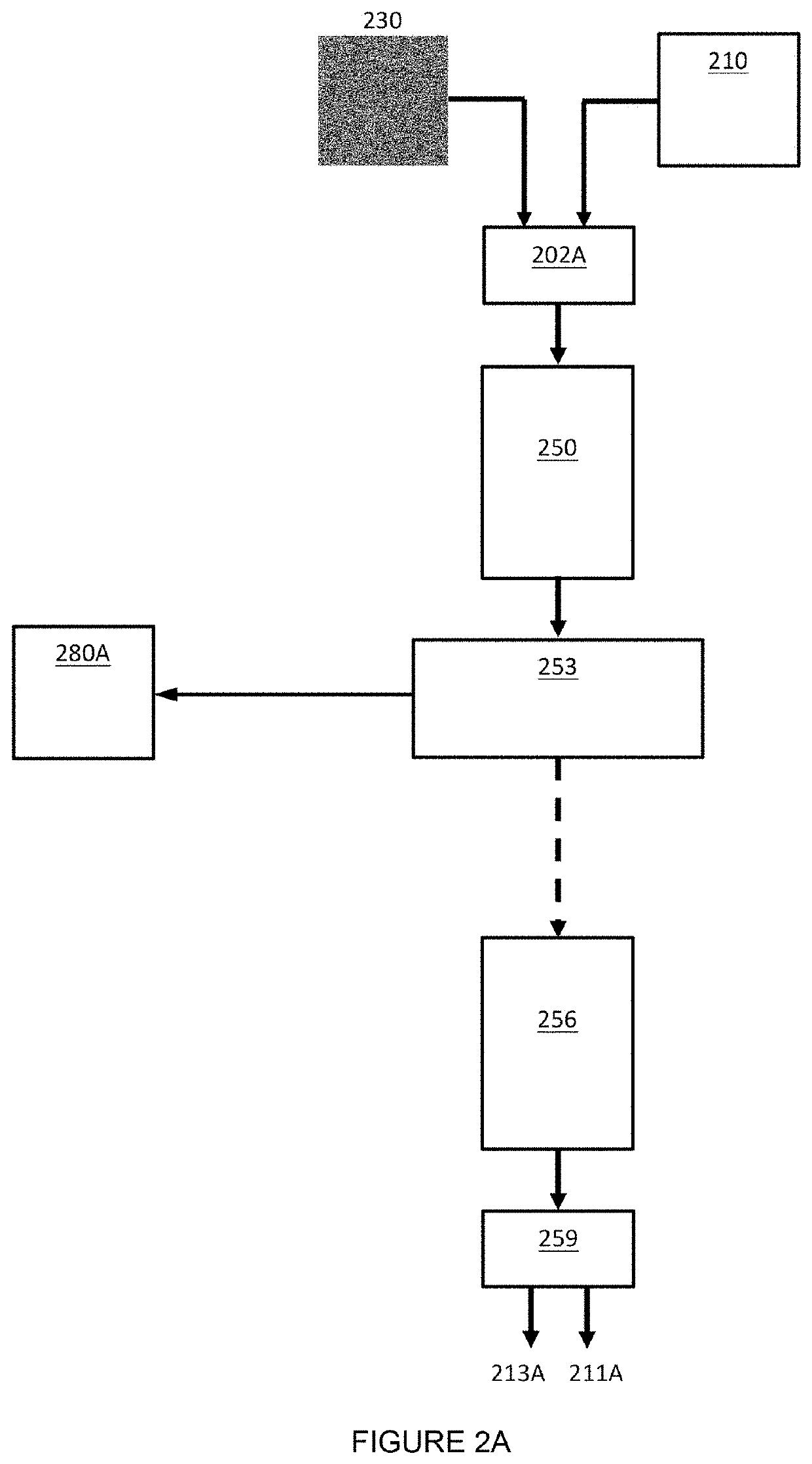
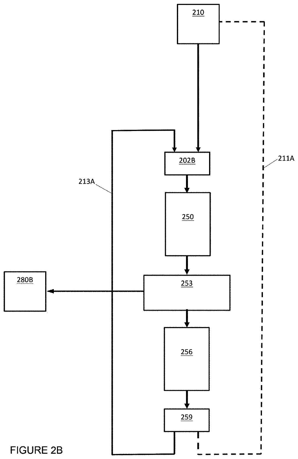
The disclosure provides in one aspect a head-up display for a vehicle. The head-up display comprises a picture generating unit, an optical system and a light-selective filter. The picture generating unit is arranged to display a picture on a screen. The optical system is arranged to receive light of the picture. The optical system comprises at least one optical element having optical power arranged to form a magnified image of the picture. The light-selective filter is transmissive to light of the picture and reflective to other light. The light-selective filter is disposed between the optical system and the screen. The light-selective filter has a first surface arranged to receive light from the optical system and a second surface arranged to receive light of the picture from the screen.

Description

CROSS-REFERENCE TO RELATED APPLICATIONS[0001]This application claims the benefit of priority of United Kingdom Patent Application no. 1815823.8, filed Sep. 28, 2018, which is hereby incorporated herein by reference in its entirety.FIELD[0002]The present disclosure relates to a display device such as an image projector or, more specifically, a virtual image projector. The present disclosure relates to a head-up display and a method of head-up display. More specifically, the present disclosure relates to a method of improving image quality in a head-up display such as a method of sunlight mitigation in a head-up display.BACKGROUND AND INTRODUCTION[0003]Light scattered from an object contains both amplitude and phase information. This amplitude and phase information can be captured on, for example, a photosensitive plate by well-known interference techniques to form a holographic recording, or “hologram”, comprising interference fringes. The hologram may be reconstructed by illuminatio...

Claims


Application Information

Patent Timeline
Patent Type & Authority Applications(United States)
IPC IPC(8): G02B27/22G03H1/22G09F19/12G02B27/01G03B21/28G09F13/12
CPCG02B30/56G09F13/12G03B21/28G02B27/0149G09F19/12G03H1/2294G03H1/2205G03H2001/221G03H2223/24G03H2223/15G02B27/0103G02B2027/0118G02B2027/0112G02B5/20G02B27/01
Inventor COLE, ALEXANDER
Owner ENVISICS LTD
Learn More