


Quick Research
Generate reliable direction feasibility study reports for your R&D in just a few steps.

Technical Q&A
Discover and master advanced knowledge NOW. Basics, ideas, possibilities, all at once.

Find Solutions
As an expert in R&D theories, this can generate solutions to your technical problems instantly.

Evaluate Feasibility
Analyze your overall solution with one click, know your potential R&D risks in advance.

Monitor Landscape
Get weekly tech updates, stay abreast of the latest tech innovations and key insights.
Nondestructive testing device and nondestructive testing method for bridge pile foundation
A non-destructive testing and pile foundation technology, applied in the analysis of materials, the use of sonic/ultrasonic/infrasonic waves to analyze solids, instruments, etc., can solve problems such as bridge testing not being able to be carried out normally
- Summary
- Abstract
- Description
- Claims
- Application Information
AI Technical Summary
Problems solved by technology
Method used
Image

Examples
Embodiment 1
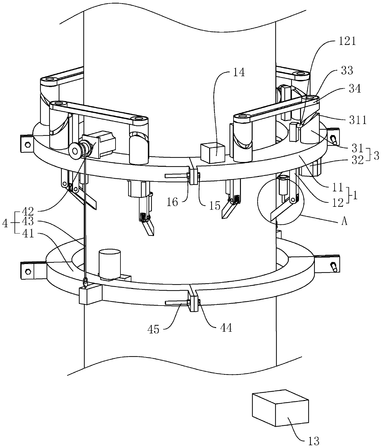
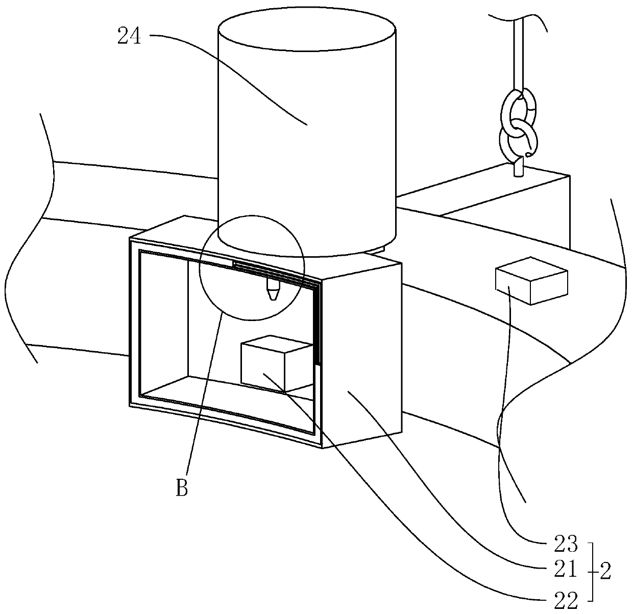
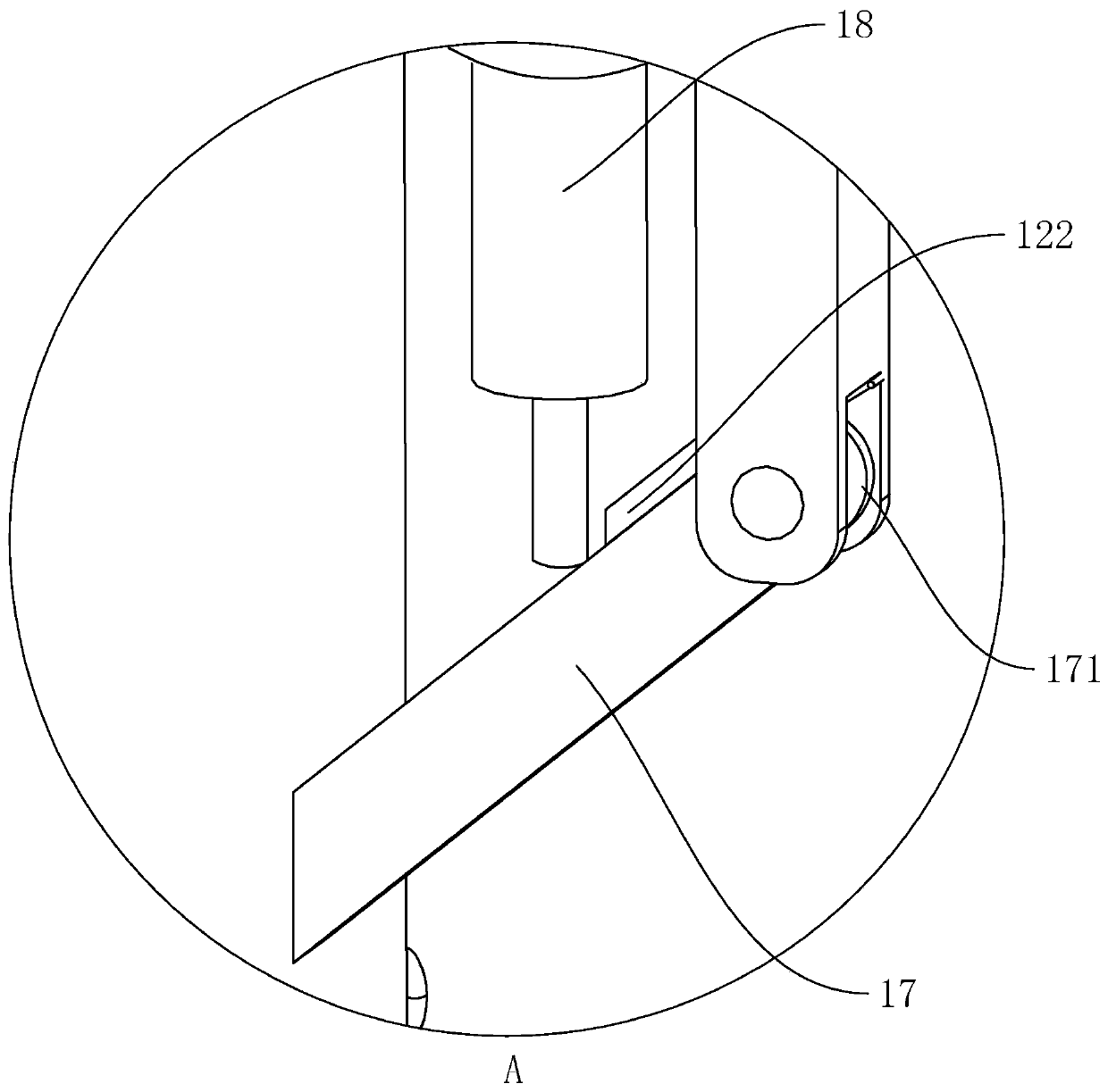
[0038] Embodiment 1: as figure 1 As shown, it is a bridge pile foundation non-destructive testing device disclosed by the present invention, which includes a climbing mechanism 1 climbing along the pile foundation and a detection mechanism 2 connected with the climbing mechanism 1. The climbing mechanism 1 includes four connecting arcs arranged around the pile foundation 11. A plurality of legs 12 connected to the connection arc 11, a drive mechanism 3 for driving the legs 12 to move back and forth in opposite directions, and a controller 13 for controlling the start and stop of the drive mechanism 3, and the controller 13 is connected to the drive mechanism 3 by wires. The number of supporting legs 12 is eight, every two supporting legs 12 are slidably connected with a connecting arc 11, and the lower ends of the supporting legs 12 are connected with the side wall of the pile foundation. like figure 2As shown, the detection mechanism 2 includes two water storage tanks 21 co...
Embodiment 2
[0047] Embodiment 2: a kind of bridge pile foundation non-destructive testing method, comprises the following steps:
[0048] S1: Set the connecting arc 11 around the pile foundation and connect the adjacent connecting arcs 11, and make the lower end of the abutment plate 17 abut against the side wall of the pile foundation, surround the detection arc 41 around the pile foundation and connect the adjacent detection arcs 41 Connect the connecting rope 43 of the hoist 42 to the upper end of the detection arc 41, and inject clear water into the water storage tank and the water storage bucket 24;
[0049] S2: The controller 13 controls the motor 32 to start rotating, the climbing mechanism 1 climbs to the top of the pile foundation, and then the controller 13 controls the hoist 42 to start at intervals, driving the detection arc 41 to move upward intermittently, and the detection mechanism 2 detects the pile foundation at the same time;
[0050] S3: After the detection is complete...
PUM
 Abstract
Description
Claims
Application Information
 - R&D Engineer
- R&D Manager
- IP Professional
- Industry Leading Data Capabilities
- Powerful AI technology
- Patent DNA Extraction
Browse by: Latest US Patents, China's latest patents, Technical Efficacy Thesaurus, Application Domain, Technology Topic, Popular Technical Reports.
© 2024 PatSnap. All rights reserved.Legal|Privacy policy|Modern Slavery Act Transparency Statement|Sitemap|About US| Contact US: help@patsnap.com