
An underwater concrete pouring device and construction method and its application in super large deep water caisson foundation

A technology of underwater concrete and construction methods, which is applied in basic structure engineering, caissons, buildings, etc., can solve the problems of no strength, economic decline of underwater structure construction, limited impact of post-poured concrete, etc., and achieve good fluidity Effect

Active Publication Date: 2022-04-22
SOUTHEAST UNIV +1
View PDF3 Cites 2 Cited by
  • Summary
  • Abstract
  • Description
  • Claims
  • Application Information

AI Technical Summary

Problems solved by technology

The results of engineering practice show that the impact effect of post-poured concrete is very limited at this time, and the expected effect cannot be achieved. There is still an obvious loose layer with scattered aggregates and no strength at the root of the caisson shaft wall.
[0008] Adding flocculants to prepare anti-dispersion concrete can significantly reduce the harm of water washing, which is a more commonly used method in current research. However, while the stability is improved, the flow performance and gap passing performance of anti-dispersion concrete are significantly reduced. However, for the ultra-large deep-water caisson foundation with a large number of complex structures such as horizontal stiffeners, horizontal ring plates, and horizontal stiffening trusses installed inside the shaft wall, the ability to climb over and wrap these structures is insufficient, which may easily cause grouting and filling. The construction quality of the well foundation; at the same time, the price of anti-dispersion concrete is high, and the construction economy of super large deep-water caisson foundation underwater structure will be significantly reduced if anti-dispersion concrete is used in all, which is not conducive to the control of project cost

Method used


Image

  • An underwater concrete pouring device and construction method and its application in super large deep water caisson foundation
  • An underwater concrete pouring device and construction method and its application in super large deep water caisson foundation
  • An underwater concrete pouring device and construction method and its application in super large deep water caisson foundation

Examples


Embodiment 1

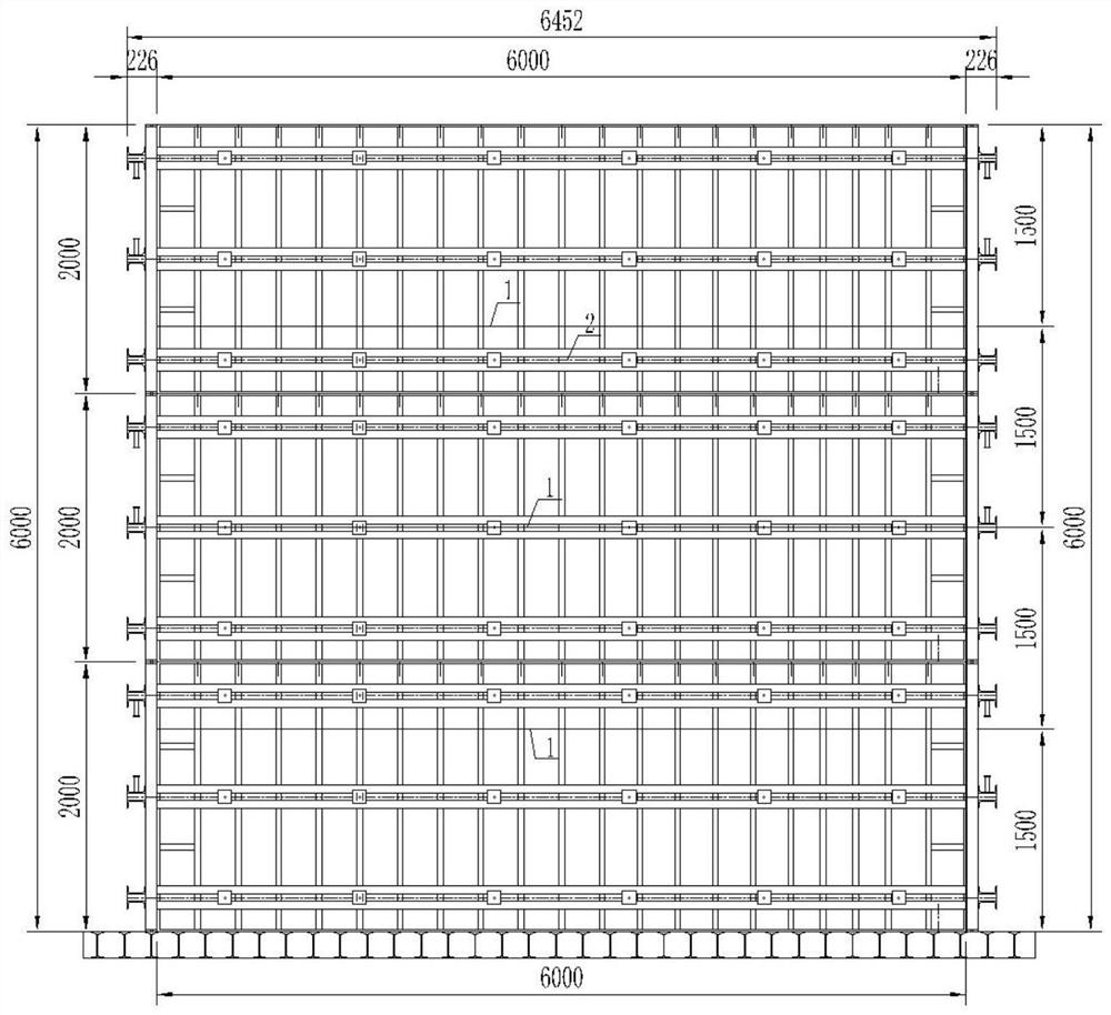
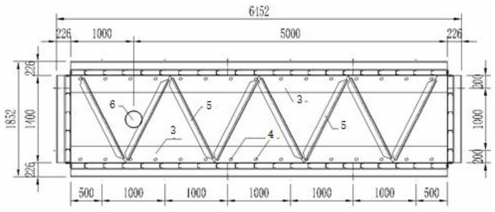
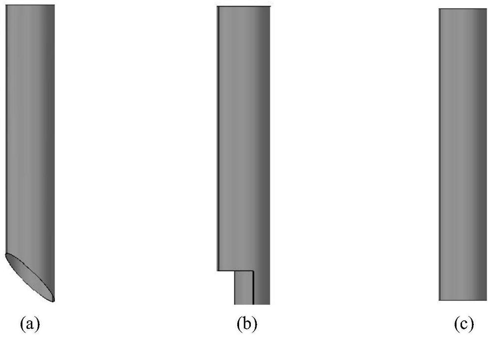
[0044] Such as figure 1 and figure 2 As shown, a full-scale model test simulating an actual project is carried out to evaluate the implementation effect of the underwater concrete construction method for the ultra-large deep-water caisson foundation provided by the present invention. The net size of the model is 6m (length) × 6m (height) × 1.4m (width). The interior is equipped with a horizontal truss composed of an 8mm thick ring plate with a 55mm@400mm overflow hole and an angle steel plate of ∠75×6mm. It is temporarily welded with side forms to form an integral structure. A total of 3 horizontal trusses are arranged in the height direction of the model, with a spacing of 1500mm. One side of the ring plate is welded to the formwork panel, and the other side of the ring plate is not welded to the formwork panel. A 325mm perfusion catheter is set on one side of the model, and the opening at the bottom of the catheter is as follows: image 3 As shown in (a), it is the obliq...


PUM


Abstract

The invention discloses an underwater concrete pouring device and construction method and its application in super large deep water caisson foundations. The underwater concrete pouring device of the present invention is composed of several pouring conduits, and the pouring conduits are provided with side openings or oblique openings. The steps of the underwater concrete construction method are as follows: first pour anti-dispersion concrete, cover the well wall and the bottom of the base, and then stop for 5-10 minutes; then pour self-compacting concrete. The underwater concrete construction method of the present invention is suitable for the construction of super large deep water caisson foundations, and can effectively solve the problems that the underwater concrete of super large deep water caisson foundations is easily washed and segregated, the strength is significantly reduced, and the pouring is not compact, so as to ensure the construction quality of the project.

Description

technical field [0001] The invention belongs to the technical field of underwater concrete construction, and in particular relates to an underwater concrete pouring device and a construction method and its application in super-large deep-water caisson foundations. Background technique [0002] The caisson is a shaft-shaped structure. By excavating soil in the well, it relies on its own gravity to overcome the frictional resistance of the well wall and sinks to the design elevation. Then the well wall is filled with concrete and the bottom is sealed to make it the foundation of the structure. The caisson foundation has strong integrity, good stability, large bearing area, and can withstand large vertical and horizontal loads, so it is widely used as the foundation of large bridge piers and sewage pumping stations, large equipment, civil air defense shelters, shield assembly wells, The foundation of structures such as underground lanes and stations can also be used as construc...

Claims


Application Information

Patent Timeline
Patent Type & Authority Patents(China)
IPC IPC(8): E02D15/06E02D23/00E02D27/18
CPCE02D15/06E02D23/00E02D27/18
Inventor 刘加平蒋振雄徐文李镇
Owner SOUTHEAST UNIV
Learn More