Environmentally friendly garbage automatic sorting device
An automatic classification and environmental protection technology, applied in trash cans, garbage collection, waste collection and transfer, etc., to ensure the effect of use, reduce impact, and facilitate subsequent recycling.
- Summary
- Abstract
- Description
- Claims
- Application Information
AI Technical Summary
Problems solved by technology
Method used
Image
Examples
Embodiment 1
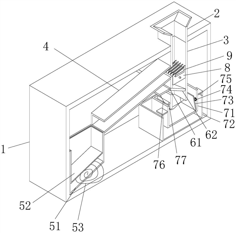
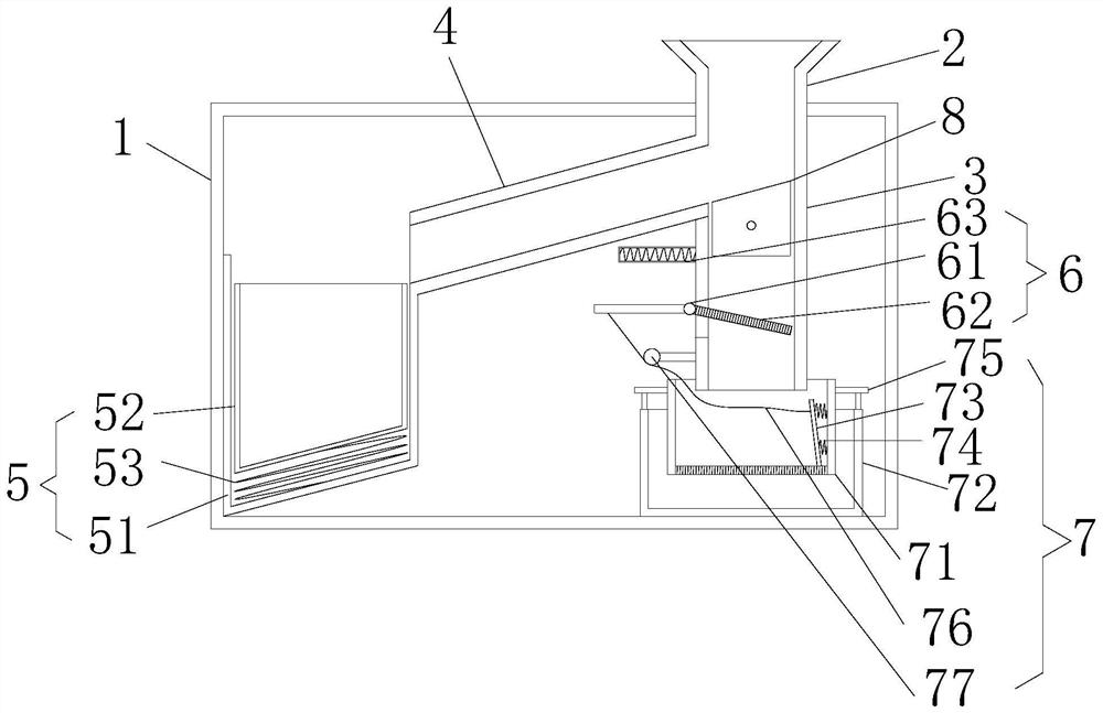
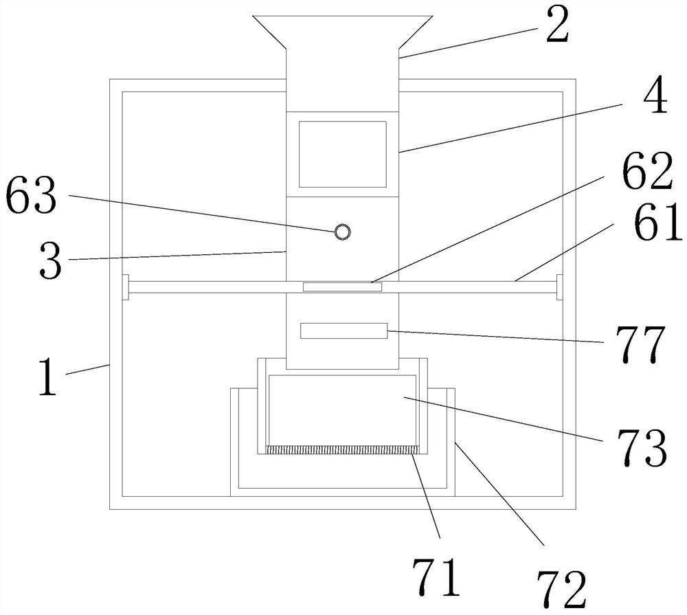
[0027] Example 1: Please refer to figure 1, an environment-friendly garbage automatic sorting device, including a sorting box 1 and a feeding port 2, the feeding port 2 is fixedly installed above the sorting box 1, and a position corresponding to the feeding port 2 on the sorting box 1 is provided with a feeding port 2 openings with matching sizes, the position corresponding to the feed port 2 in the sorting box 1 is fixedly connected with the feed pipe 3, the left side of the feed pipe 3 is provided with a feed pipe 4, and the feed pipe 4 is inclined to the The feeding pipe 3 is fixedly connected, and the position corresponding to the feeding pipe 4 on the feeding pipe 3 is penetrated. The bottom of the feeding pipe 3 is provided with a kitchen waste treatment device 7, and a cutting knife 8 is provided inside the feeding pipe 3. The number of cutting knives 8 is 10-20, and the cutting knives 8 are oblique cutting surfaces with the same inclination angle between the upper end...
Embodiment 2
[0028] Embodiment 2: On the basis of Embodiment 1, please refer to figure 1 , the bottle recovery device 5 includes a storage box 51, the storage box 51 is a square barrel with an inclined bottom, the storage box 51 is fixedly connected with the material guide pipe 4, and the storage box 51 is provided with a recovery box 52, and the recovery box 52 is The box body with the same shape as the storage box 51, the bottom of the recovery box 52 is provided with a buffer spring 53, and the two ends of the buffer spring 53 are fixedly connected with the inner wall of the storage box 51 and the bottom of the recovery box 52 respectively.
Embodiment 3
[0029] Embodiment three: on the basis of embodiment two, please refer to figure 1 , the buffer separation device 6 includes a movable rod 61, the front and rear ends of the movable rod 61 are provided with bearings and are fixedly connected with the bearing inner ring, the bearing outer rings at the front and rear ends of the movable rod 61 are fixedly connected with the front and rear inner walls of the classification box 1, the movable rod 61 One side is in contact with the left side wall of the feed pipe 3, and two movable plates 62 are fixedly installed on the movable rod 61. The length of the movable plate 62 in the interior is 1.2 times of the length of the movable plate 62 outside the feed pipe 3, and the movable plate 62 located in the feed pipe 3 is obliquely arranged. The position corresponding to the movable plate 62 in the 3 is provided with an opening whose width is four times the thickness of the movable plate 62 in the feed pipe 3, and the movable plate 62 outsi...
PUM
 Abstract
Description
Claims
Application Information
 - R&D
- Intellectual Property
- Life Sciences
- Materials
- Tech Scout
- Unparalleled Data Quality
- Higher Quality Content
- 60% Fewer Hallucinations
Browse by: Latest US Patents, China's latest patents, Technical Efficacy Thesaurus, Application Domain, Technology Topic, Popular Technical Reports.
© 2025 PatSnap. All rights reserved.Legal|Privacy policy|Modern Slavery Act Transparency Statement|Sitemap|About US| Contact US: help@patsnap.com


