Die-cutting machine with composite function

A composite function, die-cutting machine technology, applied in the lamination device, lamination auxiliary operation, lamination system, etc., can solve the problems of waste of raw materials, misalignment of raw materials, and reduced work efficiency, so as to improve work efficiency and speed of raw materials Synchronous, even gluing effect

Pending Publication Date: 2020-07-03
深圳市合联发实业有限公司
View PDF0 Cites 1 Cited by
  • Summary
  • Abstract
  • Description
  • Claims
  • Application Information

AI Technical Summary

Problems solved by technology

[0005] The purpose of the present invention is to provide a kind of die-cutting machine with composite function, to solve the problem that the existing die-cutting machine proposed in the above-mentioned background technology does not have composite function, and the raw materials need to be fed into the die-cutting machine after compounding is completed by the composite machine. Die-cutting, the process is cumbersome and labor-intensive, resulting in reduced work efficiency. The existing composite machine cannot synchronize the raw materials during feeding, which will cause the raw materials to be misplaced, resulting in the waste of raw materials.

Method used


Image

  • Die-cutting machine with composite function
  • Die-cutting machine with composite function
  • Die-cutting machine with composite function

Examples


Embodiment

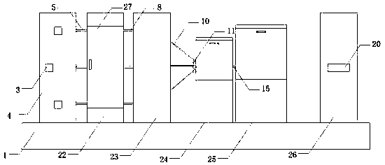
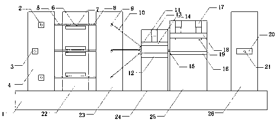
[0021] see Figure 1-3 , the present invention provides a technical solution:

[0022] A die-cutting machine with composite functions, comprising a base 1, the top wall of the base 1 is sequentially connected from left to right with a feeding block 4, a glue drying block 22, a feeding block 23, a compound block 24, a mold Cutting block 25 and material receiving block 26, three groups of rotating shafts 12 are arranged on the inner cavity of feeding block 4, and three motors 13 are arranged on the front wall of feeding block 4, and three motors 13 are respectively connected with three groups of The rotating shaft 12 is connected by a coupling, the right wall of the feeding block 4 is connected with the left wall of the gluing drying block 22 through three sets of connecting plates 5, the right wall of the gluing drying block 22 is connected with the left wall of the feeding block 23 The walls are connected by three sets of connecting plates 38, and the inner cavity of the feed...


PUM


Abstract

The invention belongs to the technical field of die-cutting machines, and concretely relates to a die-cutting machine with a composite function. The die-cutting machine comprises a base, the top wallof the base is sequentially connected with a feeding block, a gluing and drying block, a feeding block, a compounding block, a die cutting block and a collecting block from left to right. The front ends of three groups of rotating shafts I are connected with output shafts of motors I, the right wall of the feeding block is connected with the left wall of the gluing and drying block through three groups of connecting plates I, and the right wall of the gluing and drying block is connected with the left wall of the feeding block through three groups of connecting plates III. The die-cutting machine has the composite function, procedures are simplified, labor is saved, and working efficiency is improved; by adjusting the position of the rotating shafts I for placing the raw materials in the feeding block, the distances from the raw materials to the compounding block are equal, the effects that the moving speeds of the raw materials are synchronous and the raw materials are not misplaced to cause raw material waste during feeding are achieved, and the raw materials are better glued and dried during compounding through the gluing and drying device.

Description

technical field [0001] The invention relates to the technical field of die-cutting machines, in particular to a die-cutting machine with composite functions. Background technique [0002] The composite machine is to bond two or more layers of materials into one with an adhesive. Make the original materials get new functions. Such as film and aluminum foil, film, paper, non-woven fabrics, etc. are often used. It can also be compounded with film, sponge, cloth, etc. Common flexible packaging materials are basically composite products. Generally speaking, a composite machine refers to a kind of composite equipment in home textiles, clothing, furniture, automotive interiors and other related industries. It is mainly used for various types of cloth, leather, film, paper, Two-layer or multi-layer bonding production process such as sponge. Specifically, it can be divided into glue compounding and glueless compounding. Glue compounding is divided into water glue, PU oil glue, ho...

Claims


Application Information

Patent Timeline
IPC IPC(8): B32B37/12B32B37/10B32B37/06B26F1/38B26D5/12B32B38/00B32B39/00
CPCB26D5/12B26F1/38B32B37/06B32B37/10B32B37/1284B32B38/164B32B39/00
Inventor 付世凤
Owner 深圳市合联发实业有限公司
Why Eureka
Try Eureka