
Device and method for preparing metal film through area expansion in vacuum environment

A technology of area expansion and metal thin film, applied in metal processing, metal processing equipment, manufacturing tools, etc., can solve the problems of cumbersome process, many control factors, easy material consumption, etc., and achieve simple preparation process, high material utilization rate, and reliable The effect of less control variables

Active Publication Date: 2020-07-03
SHENYANG AEROSPACE UNIVERSITY
View PDF7 Cites 0 Cited by
  • Summary
  • Abstract
  • Description
  • Claims
  • Application Information

AI Technical Summary

Problems solved by technology

These methods are all through the transfer of media, depositing a film on another object. During this transfer process, no oxides can be guaranteed; because different media will cause uneven films, the quality of the generated metal films is not good. Pure, easy to produce defects; in addition, most of these preparation methods have the disadvantages of cumbersome process, low preparation efficiency, many control factors, easy consumption of materials, and easy generation of harmful gases.

Method used


Image

  • Device and method for preparing metal film through area expansion in vacuum environment
  • Device and method for preparing metal film through area expansion in vacuum environment
  • Device and method for preparing metal film through area expansion in vacuum environment

Examples


Embodiment 1

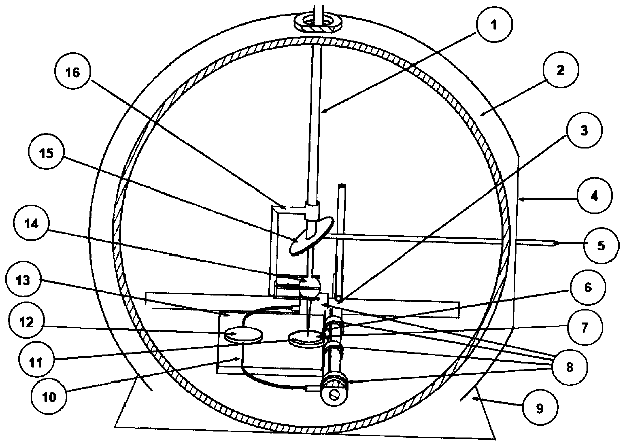
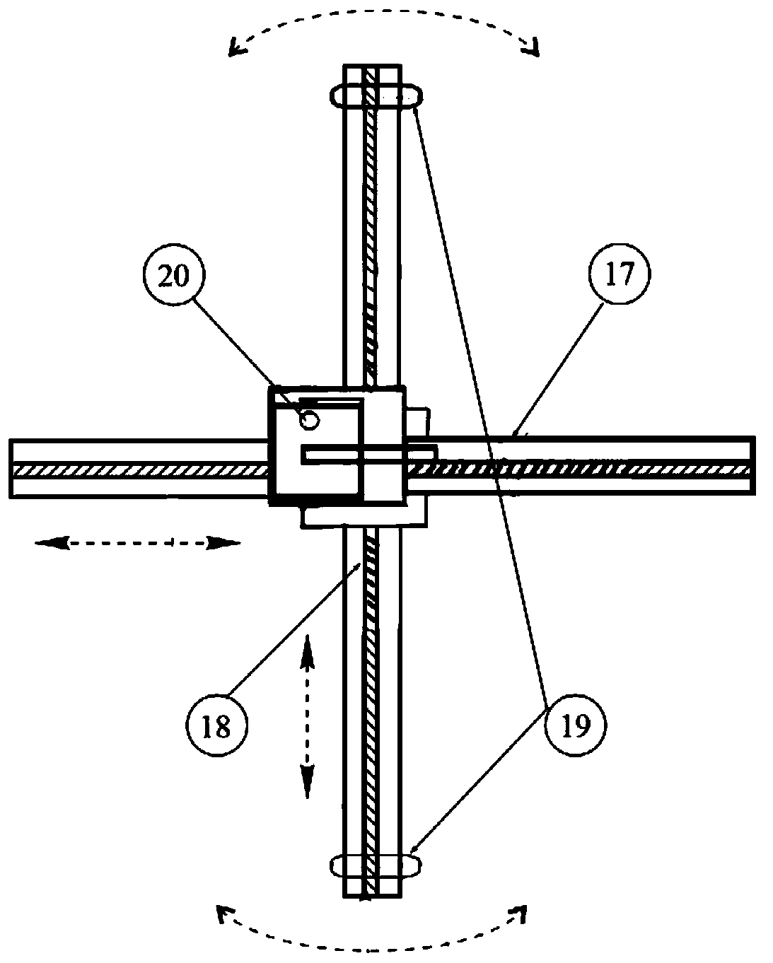
[0071] A device for preparing metal thin films by area expansion in a vacuum environment, the schematic diagram of which is shown in figure 1 Shown, comprise vacuum furnace 2, be provided with liftable test bench 13 in vacuum furnace 2, be provided with pressurization device 1 above test bench 13, pressurization device 1 is provided with reflective plane mirror 15 and converging convex lens 14, test bench 13 Fixed on the manipulator device 3, the partial top view of the manipulator device is as follows figure 2 As shown, the surface of the test bench 13 is provided with molybdenum wire rings, the molybdenum wire rings are fixed on the X-axis 18 and the Y-axis 17, the molybdenum wire rings are metal rings that can expand the area, and the molybdenum wire rings are fixed on the manipulator device 3; the manipulator device 3 includes X Axis 18, Y axis 17 and Z axis 20, the manipulator device 3 is provided with a slideway, which can realize the sliding of the XYZ axis 20, the rot...

Embodiment 2

[0081] The structure of the device for preparing a metal thin film by area expansion in a vacuum environment in this embodiment is the same as that in Embodiment 1.

[0082] The preparation process of the metal thin film is the same as in Example 1, the difference is that the 6061 aluminum alloy block is replaced by pure gallium metal, and the molybdenum wire is replaced by GH4169 superalloy wire to carry out the preparation experiment of the gallium thin film.

[0083] The experimental environment was the same as that of Example 1. A 5×5×5 mm cube of lead-tin alloy with a weight of 0.74 g was placed in the center of the furnace, and the position of the condensing convex lens was adjusted by a manipulator. According to the formula of viscosity and temperature and the calculation formula of shrinkage and viscosity, combined with the freezing point of gallium metal below 0°C, in this example, the heating temperature T(k) ranges from 30°C to 32°C (the melting point of gallium meta...

Embodiment 3

[0085] The structure of the device for preparing a metal thin film by area expansion in a vacuum environment in this embodiment is the same as that in Embodiment 1.

[0086] The metal film preparation process environment is the same as in Example 1, the difference is that the 6061 aluminum alloy block is replaced by a lead-tin alloy containing 60% tin and 40% lead, and the molybdenum wire is replaced by a GH4169 superalloy wire (which has a good comprehensive performance), to carry out the preparation experiment of lead-tin alloy thin film.

[0087] The experimental environment is the same as that of Example 1. Put a 5×5×5mm cube of lead-tin alloy with a weight of 0.55g in the center of the furnace, adjust the position of the converging convex lens with a manipulator, and calculate according to the formula of viscosity and temperature, shrinkage rate and viscosity The formula, combined with the good toughness of the lead-tin alloy, in this example, the heating temperature T(k)...


PUM

PropertyMeasurementUnit
diameteraaaaaaaaaa
thicknessaaaaaaaaaa
diameteraaaaaaaaaa

Abstract

The invention discloses a device and method for preparing a metal film through area expansion in a vacuum environment. The device comprises a vacuum furnace, wherein an experiment table is arranged inthe furnace and fixed on a manipulator device; and a pressurizing device is arranged above the experiment table, a reflecting plane mirror and a condensing convex lens are arranged on the pressurizing device, and a high-melting-point metal ring is arranged on the surface of the experiment table. According to the method, the characteristic that no air exists in the vacuum environment is utilized,a high-melting-point alloy wire is adopted to define a circle with the controllable area, one low-melting-point metal block is placed in the center of the metal ring, sunlight is gathered to melt thelow-melting-point metal block into molten metal, and the molten metal adheres to the metal wire through surface tension. Due to the fact that the vacuum environment has no heat conduction and heat convection, heat exchange can only be carried out through heat radiation, the molten metal is slow in heat dissipation and not prone to solidify, and after the temperature rises to be slightly higher than the melting point of the low-melting-point metal block, the molten metal adheres to the alloy wire due to the surface tension and gradually expands into a film along with the increase of the area ofthe metal ring; and the method is combined with the physical change of medium-free heat transfer process, the material utilization rate is high, the preparation process is simple and efficient, and environment-protecting and energy-saving, and the formed film is high in surface quality and excellent in performance.

Description

Technical field: [0001] The invention belongs to the technical field of metal thin film preparation, and in particular relates to a device and method for preparing a metal thin film by area expansion in a vacuum environment. Background technique: [0002] Due to its good plasticity, toughness and strength, high conductivity and adaptability to the environment and materials, metal thin film is one of the best film materials after organic thin film and ceramic thin film. It is used in electronic components, integrated optics, electronics Technology, infrared technology, laser technology, aerospace technology and optical instruments have been widely used in various fields, especially in the field of lightweight and high-strength material thin film applications, they have become independent application technologies, and have become important materials for surface modification and improvement. It is an important means of certain technological level, which makes the preparation of...

Claims


Application Information

Patent Timeline
Patent Type & Authority Applications(China)
IPC IPC(8): B21D33/00B21D37/16B21C51/00
CPCB21C51/00B21D33/00B21D37/16
Inventor 王悦王继杰王志伟农智升刘春忠刘兴民邓希光卢少微李壮
Owner SHENYANG AEROSPACE UNIVERSITY
Learn More