Microlens assembly, preparation method, optical fingerprint module and electronic device

A micro-lens and micro-lens array technology, applied in the field of micro-lenses, can solve the problems of reducing the strength of transparent substrates, affecting the layout of diodes, etc.

Inactive Publication Date: 2020-06-30
NANCHANG OUFEI BIOLOGICAL IDENTIFICATION TECH
View PDF0 Cites 3 Cited by
  • Summary
  • Abstract
  • Description
  • Claims
  • Application Information

AI Technical Summary

Problems solved by technology

However, this method needs to change the structure of the transparent substrate, resulting in a decrease in the strength of the transparent substrate, and may also affect the layout of components such as diodes on the transparent substrate.

Method used


Image

  • Microlens assembly, preparation method, optical fingerprint module and electronic device
  • Microlens assembly, preparation method, optical fingerprint module and electronic device
  • Microlens assembly, preparation method, optical fingerprint module and electronic device

Examples


Embodiment Construction

[0040] In order to make the above objects, features and advantages of the present invention more comprehensible, specific implementations of the present invention will be described in detail below in conjunction with the accompanying drawings. In the following description, numerous specific details are set forth in order to provide a thorough understanding of the present invention. However, the present invention can be implemented in many other ways different from those described here, and those skilled in the art can make similar improvements without departing from the connotation of the present invention, so the present invention is not limited by the specific embodiments disclosed below.

[0041] It should be noted that when an element is referred to as being “fixed” to another element, it can be directly on the other element or there can also be an intervening element. When an element is referred to as being "connected to" another element, it can be directly connected to t...


PUM

PropertyMeasurementUnit
Thicknessaaaaaaaaaa

Abstract

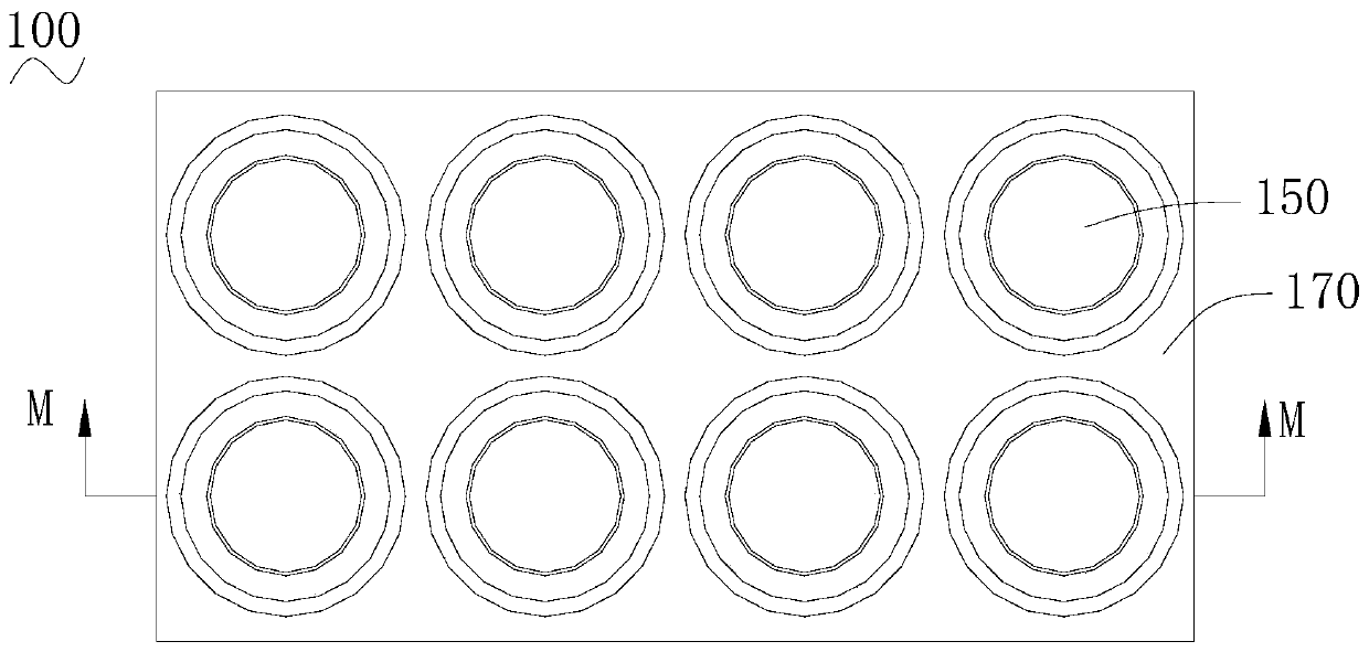
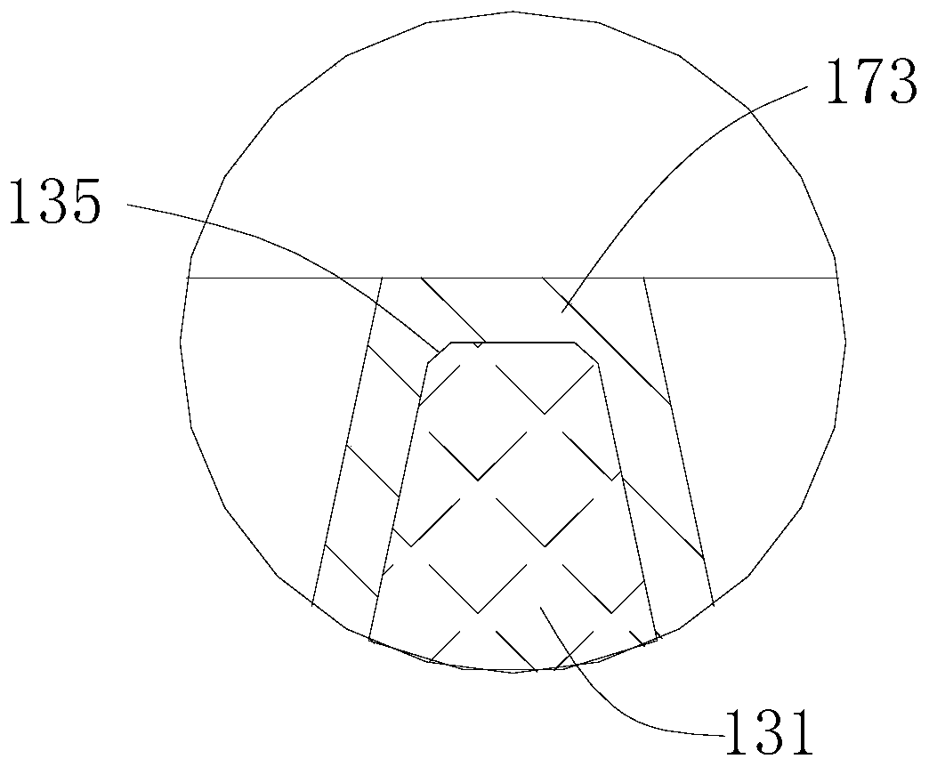
The invention relates to a micro-lens assembly, a preparation method, an optical fingerprint module and an electronic device. The micro-lens assembly includes a transparent substrate; an imprinting base which is arranged on the transparent substrate, wherein bulges are arranged on the surface, far away from the transparent substrate, of the imprinting substrate, and a plurality of non-communicatedrecesses are defined by the bulges; a micro-lens array which comprises a plurality of micro-lenses which are arranged on the surface, far away from the transparent substrate, of the imprinting base and are arranged in an array, wherein the micro-lenses are in one-to-one correspondence with the recesses, and the micro-lenses are located in the recesses; a shading layer which completely covers thepart, which is not covered by the micro lenses, of the imprinting substrate and partially covers the micro-lenses; a shading layer which is provided with a plurality of hollow structures in one-to-onecorrespondence with the micro-lenses; in the direction perpendicular to the working surface, the central axis of the hollow structure is collinear with the central axis of the corresponding micro-lenses; in the direction perpendicular to the working face, the projection of the hollow structure on the micro-lenses completely falls on the micro-lenses, and a gap is formed between the projection ofthe hollow structure and the edge of the micro-lenses.

Description

technical field [0001] The invention relates to the field of microlenses, in particular to a microlens component, a preparation method, an optical fingerprint module and an electronic device. Background technique [0002] A microlens array refers to a number of micro-nano-scale lens groups arranged in an array. It not only has the basic functions of focusing and imaging of traditional lenses, but also has the characteristics of small unit size and high integration, which enables it to complete functions that traditional optical components cannot complete, and can constitute many new optical systems. Generally, in order to prevent light with a large oblique angle from entering the microlens and then passing through the imprinted substrate to form an image, grooves are often arranged on the transparent substrate, and a light-shielding material is arranged in the groove to block the incident oblique angle. larger light. However, this method needs to change the structure of th...

Claims


Application Information

Patent Timeline
IPC IPC(8): G06K9/00G02B3/00
CPCG02B3/0037G02B3/0012G06V40/1324
Inventor 刘伟郑刚强任金虎黄梅峰
Owner NANCHANG OUFEI BIOLOGICAL IDENTIFICATION TECH
Why Eureka
Try Eureka