
Conveyor and conveying method

A conveyor and conveyor belt technology, applied in the field of conveyors, can solve the problems of inconsistent speed of conveyors, rolling up of soft and thin materials, and inability to meet production needs, and achieve the effect of synchronous transmission

Inactive Publication Date: 2020-06-30
长园装备制造有限公司
View PDF7 Cites 0 Cited by
  • Summary
  • Abstract
  • Description
  • Claims
  • Application Information

AI Technical Summary

Problems solved by technology

[0003] However, multiple teleporters may have inconsistent speeds
For example, the transmission speed of the previous conveyor is greater than that of the next conveyor, and when the material is transferred from the conveyor with a high transmission speed to the conveyor with a low transmission speed, due to inertia, soft and thin materials will be rolled up. situation, unable to meet production demand

Method used


Image

  • Conveyor and conveying method
  • Conveyor and conveying method
  • Conveyor and conveying method

Examples


Embodiment 1

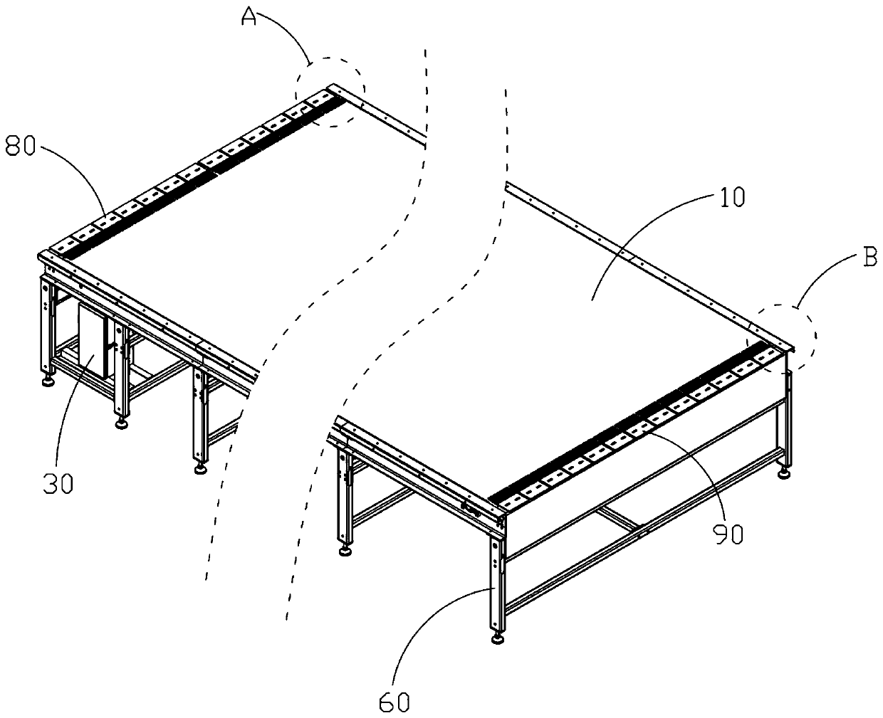
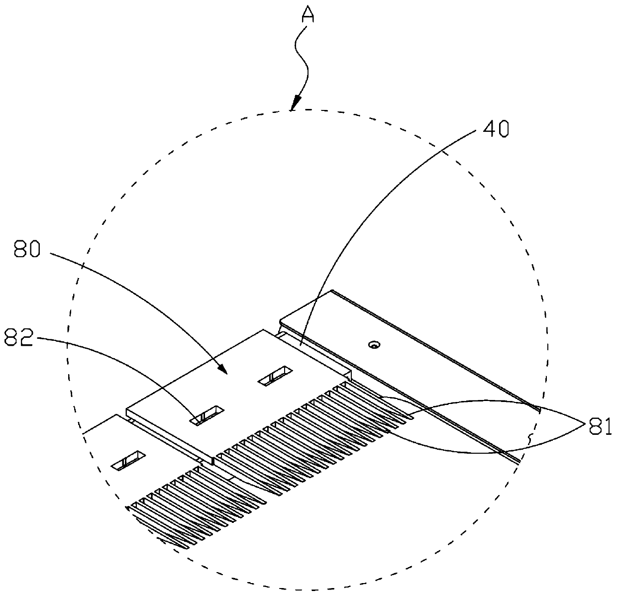
[0044] figure 1 A schematic diagram of a conveyor provided by an embodiment of the present invention, figure 2 A structural schematic diagram of a conveyor provided by an embodiment of the present invention, image 3 for figure 2 A magnified view of region A in the middle, Figure 4 for figure 2 Enlarged view of region B in the middle.

[0045] like Figure 1 to Figure 4 As shown, the present embodiment provides a conveyor, including:

[0046] Conveyor belt 10, the conveyor belt 10 is used for conveying materials;

[0047] A motor 20, the motor 20 is connected with the conveyor belt 10 to drive the conveyor belt 10 to move;

[0048] The electric control device 30 is electrically connected with the motor 20 and used to control the rotation of the motor 20;

[0049] A position sensor 40, the position sensor 40 is located at the discharge end of the conveyor and is electrically connected with the electric control device 30, and is used to detect whether the material re...

Embodiment 2

[0055] like figure 2 As shown, the conveyor provided in this embodiment further includes a frame 60 on which the conveyor belt 10 , the motor 20 , the electric control device 30 , the position sensor 40 and the speed sensor 50 are all arranged.

[0056] Frame 60 is used to provide support for the various components of the conveyor.

Embodiment 3

[0058] In this embodiment, the speed sensor 50 is located at the infeed end or side of the conveyor.


PUM


Abstract

The invention relates to the technical field of conveyors, in particular to a conveyor and a conveying method. The conveyor comprises a conveying belt, a motor, an electrical device, a position sensor, and a speed sensor, wherein the conveying belt is used for conveying a material; the motor is connected with the conveying belt so as to drive the conveying belt to move; the electric control deviceis electrically connected with the motor and used for controlling the motor to rotate; the position sensor is located at the discharging end of the conveyor, electrically connected with the electriccontrol device and used for detecting whether the material reach the designated position or not; and the speed sensor is electrically connected with the electric control device and used for detectingthe conveying speed of a next conveyor. Through the above arrangement, when the material is conveyed to the designated position, the electric control device can adjust the conveying speed of the electric control device to be the same as the conveying speed of the next conveyor according to the conveying speed, detected by the speed sensor, of the next conveyor, so that synchronous conveying is achieved.

Description

technical field [0001] The invention relates to the technical field of conveyors, in particular to a conveyor and a conveyor method. Background technique [0002] Today, the textile industry has achieved automated production. In the production workshop, multiple conveyors are generally used to convey materials one after another, and convey soft and thin materials such as cloth and leather to the target position. [0003] However, multiple conveyors may have inconsistent speeds. For example, the transmission speed of the previous conveyor is greater than that of the next conveyor, and when the material is transferred from the conveyor with a high transmission speed to the conveyor with a low transmission speed, due to inertia, soft and thin materials will be rolled up. The situation cannot meet the production demand. Contents of the invention [0004] The main purpose of the present invention is to provide a conveyor and a conveying method that do not roll up when convey...

Claims


Application Information

Patent Timeline
Patent Type & Authority Applications(China)
IPC IPC(8): B65G43/08B65G15/30
CPCB65G15/30B65G43/08B65G2203/0291
Inventor 程翱翔
Owner 长园装备制造有限公司
Learn More