A control device for a robot
A control device and robot technology, applied in the direction of manipulators, manufacturing tools, etc., can solve the problems of single action of the manipulator and shorten the processing time.
- Summary
- Abstract
- Description
- Claims
- Application Information
AI Technical Summary
Problems solved by technology
Method used
Image
Examples
Embodiment 1
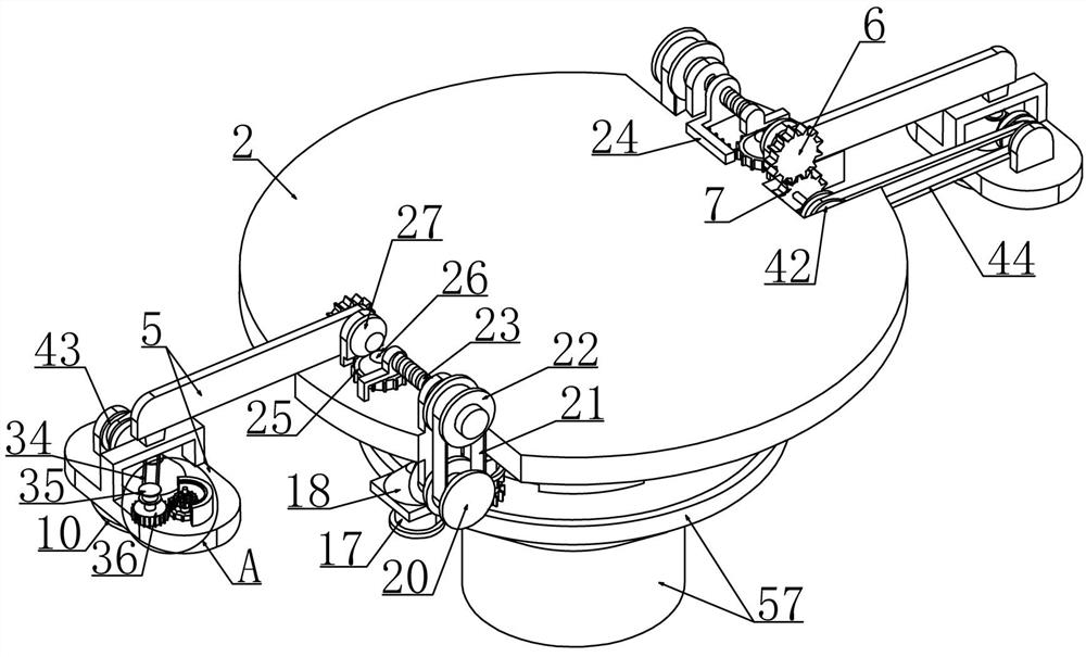
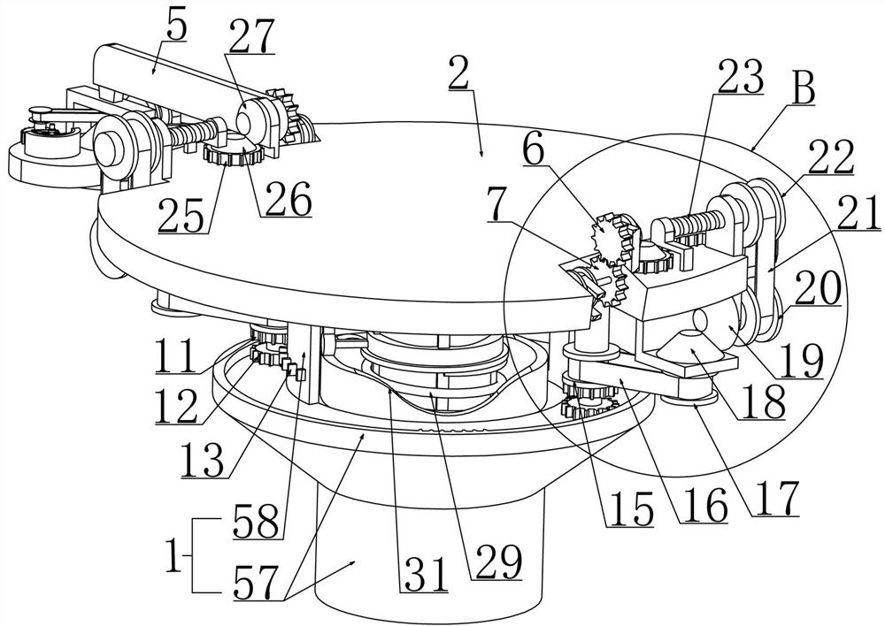
[0033] Embodiment 1, this embodiment provides a control device for a robot, which includes a base 1, referring to the attached Figure 4 As shown, a support plate 2 is rotatably installed on the base 1 and the support plate 2 is driven by a motor 3 fixedly installed on the base 1. The motor 3 is connected to an external power supply and is electrically connected to the microcontroller, and In this embodiment, the microcontroller controls the motor 3 to start intermittently, that is, the motor 3 will drive the supporting plate 2 to rotate intermittently, and two rotating shafts 4 are installed on the lateral sides of the lower end surface of the supporting plate 2, and the lower ends of the two rotating shafts 4 It is connected with a rotating shaft drive device, through which the forward and reverse rotation of the rotating shaft 4 can be controlled, and the rotating shaft 4 is connected with a transmission mechanism, through which the power of the rotating shaft 4 is changed, ...
Embodiment 2
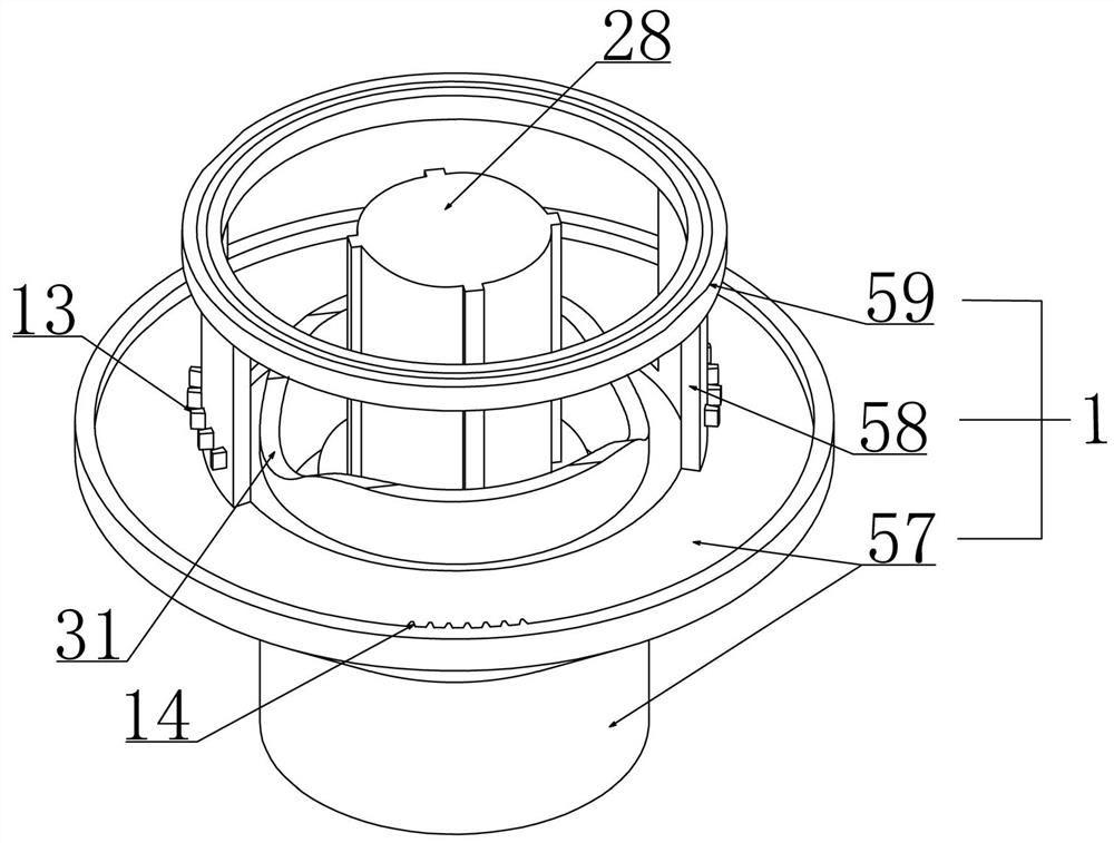
[0035] Embodiment 2, on the basis of embodiment 1, with reference to appended figure 2 As shown, the base 1 includes a fixed cylinder 57 fixedly connected to the foundation, and two arc-shaped plates 58 are fixedly installed on the upper end of the fixed cylinder 57 close to the inner circular surface, and these two arc-shaped plates 58 are radially symmetrical to the fixed cylinder 57 , and the upper ends of the two arc-shaped plates 58 are fixedly installed with a mounting ring 59 , and the supporting plate 2 is rotatably mounted on the upper end surface of the mounting ring 59 .
Embodiment 3
[0036] Embodiment 3, on the basis of Embodiment 2, in order to ensure that the support rod 5 can realize positive and negative rotation during the rotation of the support plate 2, a rotating shaft driving device is provided on the rotating shaft 4, refer to the attached Figure 7 As shown, the rotating shaft driving device includes a forward rotating helical gear 11 and a reverse rotating helical gear 12 which are vertically spaced at the lower end of the rotating shaft 4. Refer to the attached figure 2 As shown, a first helical gear train 13 corresponding to the forward-rotating helical gear 11 is provided on the arc-shaped plate 58. When the forward-rotating helical gear 11 meshes with the first helical gear train 13, it will drive the rotating shaft 4 to rotate forward. Moreover, a second helical gear train 14 corresponding to the reverse helical gear 12 is provided between the two arc-shaped plates 58 on the outer surface of the upper end surface of the fixed cylinder 57. ...
PUM
 Abstract
Description
Claims
Application Information
 - Generate Ideas
- Intellectual Property
- Life Sciences
- Materials
- Tech Scout
- Unparalleled Data Quality
- Higher Quality Content
- 60% Fewer Hallucinations
Browse by: Latest US Patents, China's latest patents, Technical Efficacy Thesaurus, Application Domain, Technology Topic, Popular Technical Reports.
© 2025 PatSnap. All rights reserved.Legal|Privacy policy|Modern Slavery Act Transparency Statement|Sitemap|About US| Contact US: help@patsnap.com


