Locking mechanism of movable connecting piece and application thereof
A technology of movable connection and locking mechanism, which is applied in the field of intelligent toilet to achieve the effect of convenient operation, single action and avoiding operation errors
- Summary
- Abstract
- Description
- Claims
- Application Information
AI Technical Summary
Problems solved by technology
Method used
Image
Examples
Embodiment 1
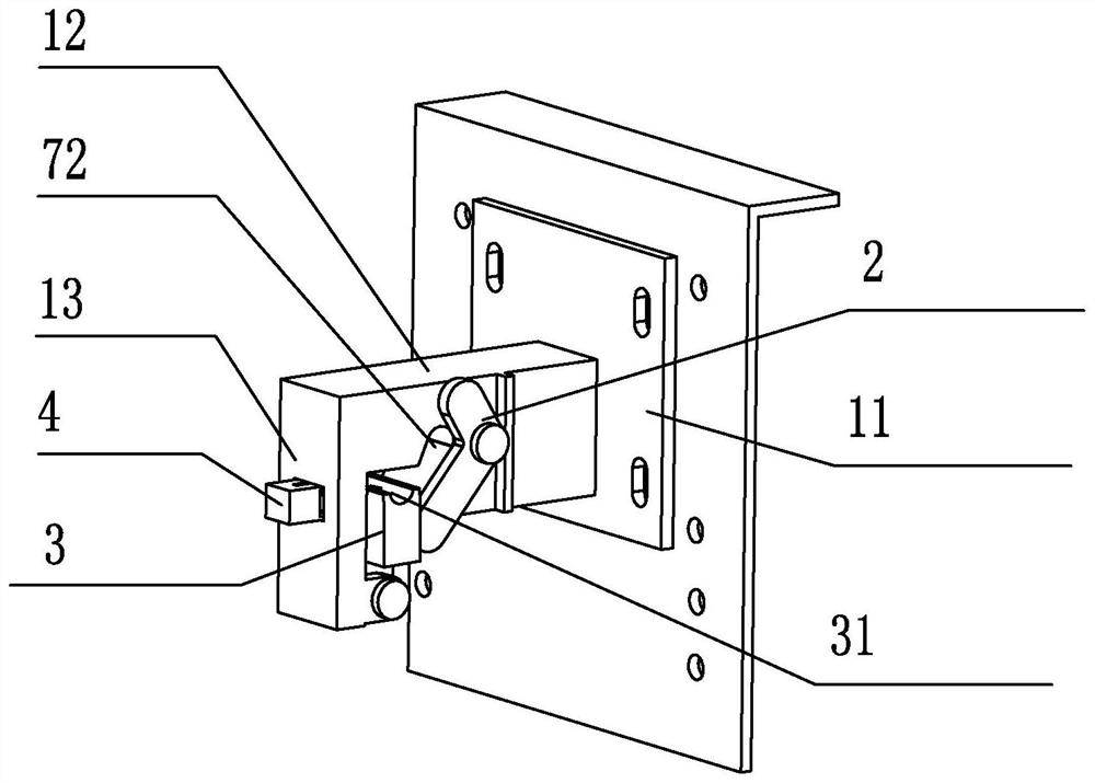
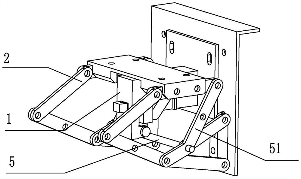
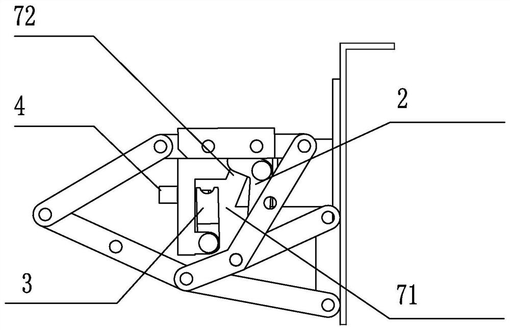
[0044] In this embodiment, a locking mechanism 64 of a movable joint includes a bracket 1, a travel switch 2, a support block 3, a push-type lock 4 and a support rod 5; the movable joint component in this embodiment is a connecting rod;
[0045] The bracket 1 is used to fix the locking mechanism 64 to the side of the connecting rod;
[0046] The travel switch 2 includes an operation end 21 and a linkage end 22, and the linkage end 22 is located below the operation end 21;
[0047] The support block 3 is pivotally connected to the bracket 1, and the support block 3 is arranged within the stroke distance of the linkage end 22 and forms a movable channel 71 with the linkage end 22;
[0048] Both ends of the support rod 5 are fixed to the connecting rod. In the initial state, the rod body of the support rod 5 penetrates the bottom of the bracket 1 and is arranged at the opening below the movable channel 71 . When the connecting rod moves, it drives the support rod 5 into and out ...
Embodiment 2
[0059] The difference between embodiment 2 and embodiment 1 is: as Figure 11 a and b, a booster spring 52 is also connected between the connecting rods.
PUM
 Abstract
Description
Claims
Application Information
 - R&D Engineer
- R&D Manager
- IP Professional
- Industry Leading Data Capabilities
- Powerful AI technology
- Patent DNA Extraction
Browse by: Latest US Patents, China's latest patents, Technical Efficacy Thesaurus, Application Domain, Technology Topic, Popular Technical Reports.
© 2024 PatSnap. All rights reserved.Legal|Privacy policy|Modern Slavery Act Transparency Statement|Sitemap|About US| Contact US: help@patsnap.com


